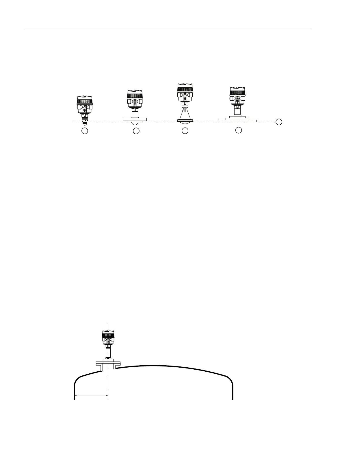
5.3 Sensor reference point
The measur
ing range of LR500 series devices begins at the end of the sensor reference point.
The reference point is dierent depending on the sensor version.
① LR510 threaded lens antenna
② LR530 ang
ed encapsulated antenna
③ LR550 polymeric horn antenna
1)
④ LR580 ang
ed lens antenna
⑤ Sensor reference point
1)
When t
he LR550 is supplied with a ange, the sensor reference point is at the bottom of
the ange.
5.4 Nozzle mounting
Nozzle location
• Avoid central locations on tall, narrow vessels
• Nozzle must be vertical and clear of imperfections
Place the mounting location of the radar sensor where no other equipment or xtures
cross the path of the radar signals. Vessel installations, such as ladders, limit switches,
heating spirals, struts, and so forth, can cause false echoes and impair the material echo.
Ensure when planning your measuring point that the radar sensor has a " clear view" to the
measured product. In case of existing vessel installations, an auto false echo suppression
should be carried out during setup when the vessel is empty.
Installing/mounting
5.4Nozzle mounting
SITRANS LR500 series with mA/HART
40 Operating Instructions, 03/2024, A5E51099898-AA
 Loading...