3. Connect wires to terminals as shown below: polarity is identied on t
erminal block.
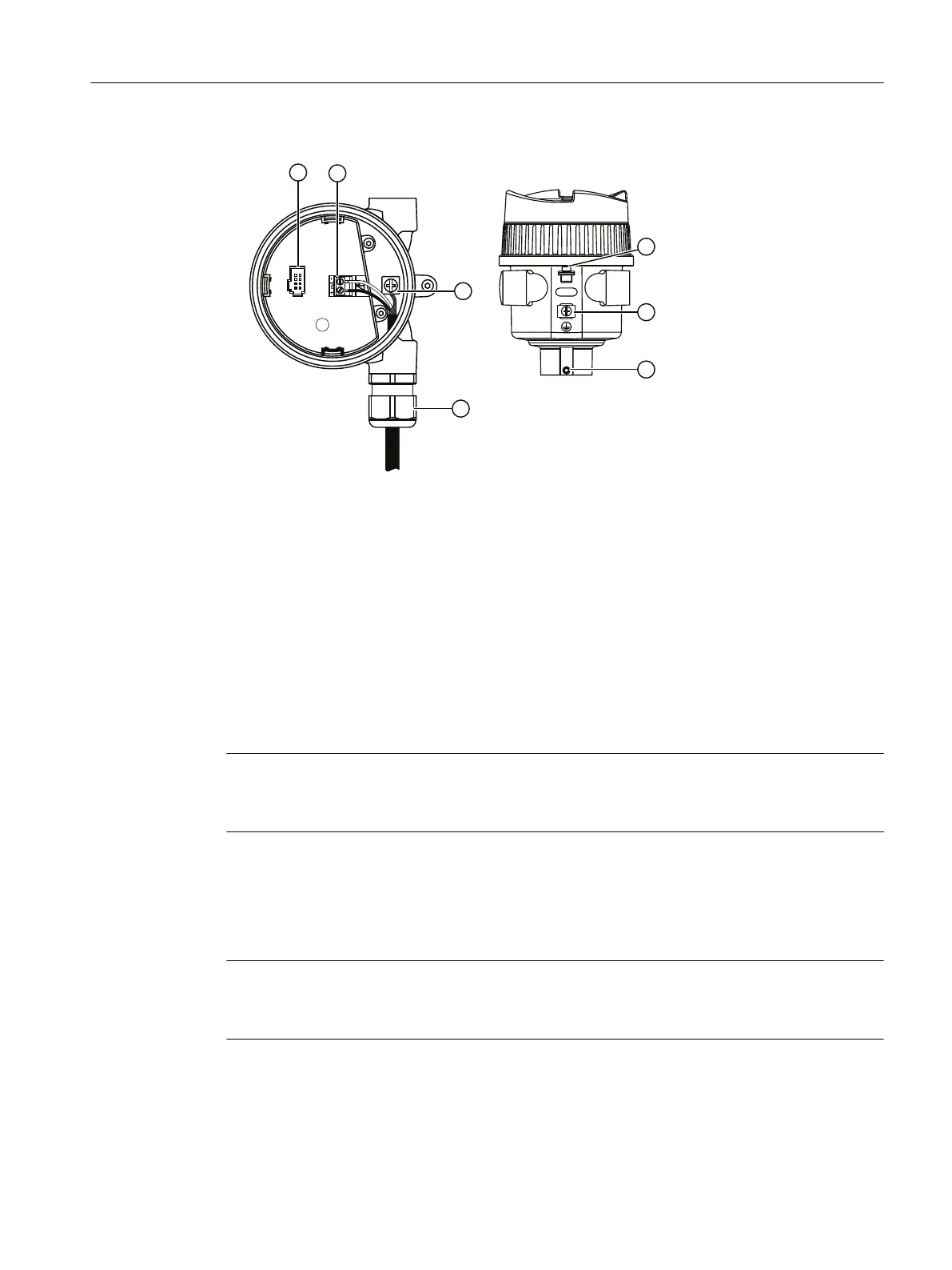
① HMI connection ⑤ Ground connection
② Instrument connection ⑥ Housing rotation lock screw
③ Lid lock screw ⑦ Cable gland (or NPT cable entry)
④ Cable shield/ground connection
4. Tighten gland to form a good seal.
5
. Press socket end of cable from optional display onto four-pin connector plug.
6. Set optional HMI into enclosure. Buttons on HMI should sit over terminal block. Replacing the
HMI (Page152)
7. Replace device lid. Thread onto enclosure, turning clockwise. Hand tighten until mechanical
stop is reached.
Note
Housing can be r
otated
Housing can be rotated beyond 360° without damaging the device.
6.2.2 Input supply cable note
Note
Insulation t
hickness
The input supply cable should have an insulation thickness of at least 0.5 mm.
Connecting
6.2Connecting SITRANS LR500 series
SITRANS LR500 series with mA/HART
Operating Instructions, 03/2024, A5E51099898-AA 53
 Loading...