Fail-safe
The fail-saf
e parameters ensure that the device defaults to an appropriate state when a valid
level reading is not available. (See Fault codes and corrective actions (Page159) for a list of
fault codes related to fail-safe.)
• Parameter "Fault current" denes the behavior (mA output value to report) when an error
condition, such as loss of echo, is detected.
• A fail-safe timer also activates when an error condition is detected. "Fail-safe LOE timer" sets
the amount of time the loss of echo will persist before device enters fail-safe mode.
• Upon expiration of the timer, and if device is still in an error condition, the mA output value
reported is based on value set in parameter "Fail-safe loss of echo".
If fail-safe operation activates frequently, see Diagnostics and troubleshooting (Page155).
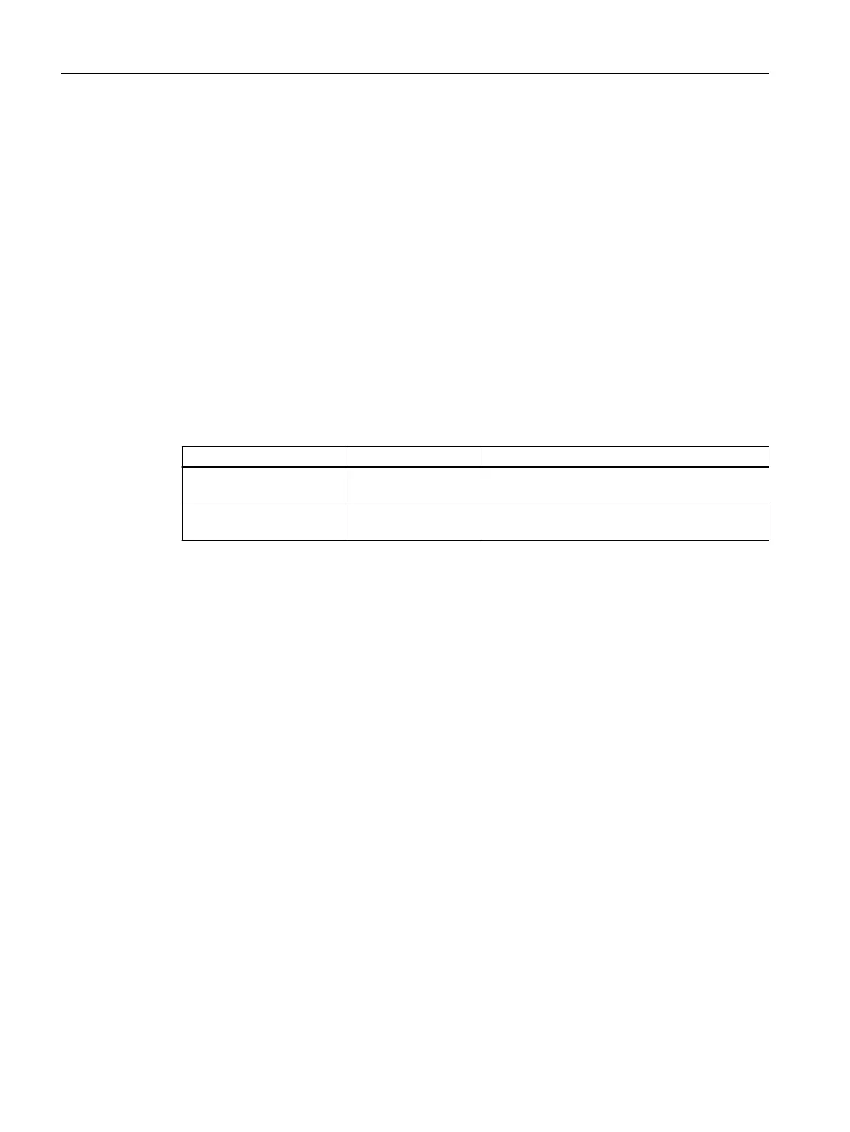
8.2 mA control
Parameter Default value Description
Lower saturation limit 3.8 Set lower limit for saturation range, past which the
loop cur
rent cannot decrease.
Upper saturation limit 20.5 Set upper limit for saturation range, past which
t
he loop current cannot increase.
Verifying the mA range
Chec
k that the external device can track the entire 4 to 20 mA range sent by the device.
Follow the steps below if actual mA readings dier between the device (shown under "Loop
current" in measurement view of device) and an external device (such as a PLC).
1. To test the loop current, run the "Loop test wizard". Select a constant mA value to use in the
test from a list of mA values, or set a custom mA value by selecting option "User", then set a
value.
2. Check that the external device displays the same mA reading as the mA value set above.
3. If external device reading diers from the value manually set on the device, adjust the
reading on the external device to match the reading on the device.
8.3 Characterization chart
If you wish to measure volume and you cannot use a pre-dened vessel (Vessel shape (2.5.1)
(Page123)), you must congure a custom application.
Congure a custom application by setting parameter "Operation" (in quick commissioning
wizard), or "PV selection" (in navigation view) to option "Custom", then dene your
vessel/PMD using Customized characteristic curve (2.6.2) (Page126).
Up to 32 breakpoints, each consisting of an input and output value (X- and Y-value), are
available to dene your vessel shape.
• For a custom volume characteristic curve, X-values refer to level, Y-values refer to volume.
Operating
8.3Characterization chart
SITRANS LR500 series with mA/HART
86 Operating Instructions, 03/2024, A5E51099898-AA
 Loading...