10.1 Introduction
The safety settings consist of a number of limit values used to constrain the movements of the robot
arm, and of safety function settings for the configurable inputs and outputs. They are defined in
the following subtabs of the safety screen:
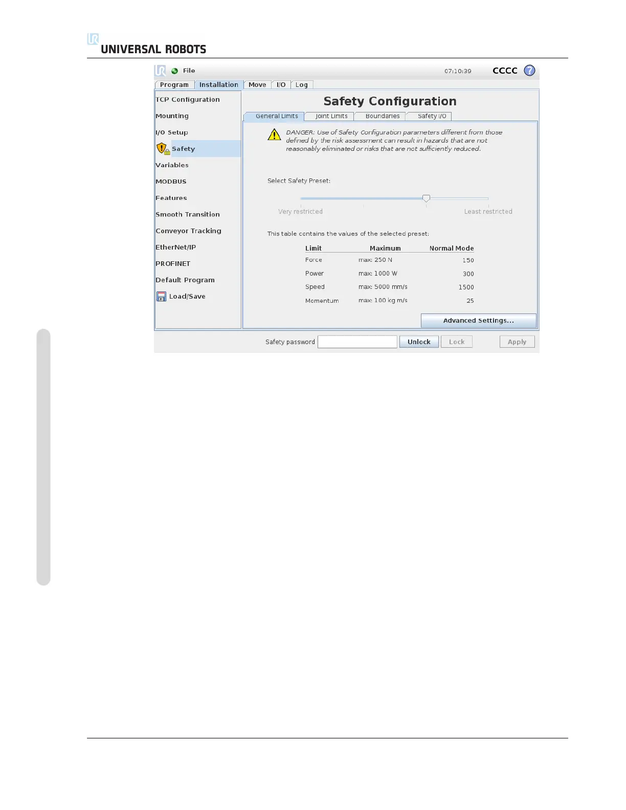
• The General Limits subtab defines the maximum force, power, speed and momentum of the
robot arm. When the risk of hitting a human or colliding with a part of its environment is
particularly high, these settings need to be set to low values. If the risk is low, higher general
limits enable the robot to move faster and exert more force on its environment. For further
details, see 10.10.
• The Joint Limits subtab consists of joint speed and joint position limits. The joint speed limits
define the maximum angular velocity of individual joints and serve to further limit the speed
of the robot arm. The joint position limits define the allowed position range of individual joints
(in joint space). For further details, see 10.11.
• The Boundaries subtab defines safety planes (in Cartesian space) and a tool orientation
boundary for the robot TCP. The safety planes can be configured either as hard limits for the
position of the robot TCP, or triggers for activating the Reduced mode safety limits (see 10.6)).
The tool orientation boundary puts a hard limit on the orientation of the robot TCP. For further
details, see 10.12.
• The Safety I/O subtab defines safety functions for configurable inputs and outputs (see 13.2).
For example, Emergency Stop can be configured as an input. For further details, see 10.13.
CB3 II-4 Version 3.10
Copyright © 2009–2019 by Universal Robots A/S. All rights reserved.

 Loading...


