5.4 Tool I/O
5.4.2.1 Using the Tool Digital Inputs
The example below shows how to connect a simple button.
5.4.3 Tool Analog Inputs
The tool analog inputs are non-differential and can be set to either voltage and current on the I/O
tab, see part II. The electrical specifications are shown below.
Parameter Min Typ Max Unit
Input voltage in voltage mode -0.5 - 26 V
Input resistance @ range 0V to 10V - 15 - kΩ
Resolution - 12 - bit
Input voltage in current mode -0.5 - 5.0 V
Input current in current mode -2.5 - 25 mA
Input resistance @ range 4mA to 20mA - 200 - Ω
Resolution - 12 - bit
Two examples of how to use analog inputs are shown in the following subsections.
CAUTION:
1. Analog inputs are not protected against over voltage in current
mode. Overrating the limit in the electrical specification can
cause permanent damage to the input.
5.4.3.1 Using the Tool Analog Inputs, Non-differential
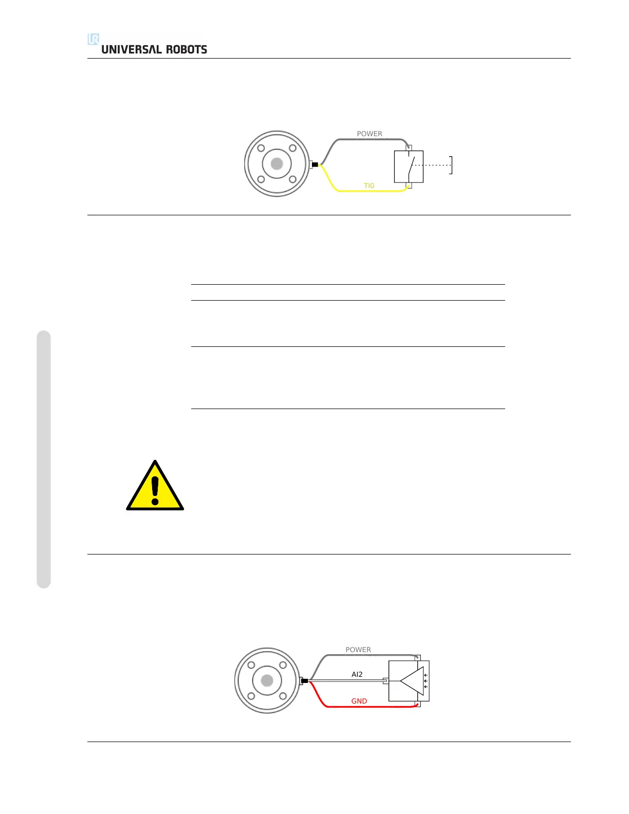
The example below shows how to connect an analog sensor with a non-differential output. The
output of the sensor can be either current or voltage, as long as the input mode of that analog input
is set to the same on the I/O tab. Remember to check that a sensor with voltage output can drive
the internal resistance of the tool, or the measurement might be invalid.
UR3/CB3 I-44 Version 3.10
Copyright © 2009–2019 by Universal Robots A/S. All rights reserved.

 Loading...


