EasyManua.ls Logo

Universal Robots UR3/CB3 User Manual

Universal Robots UR3/CB3
256 pages
To Next Page IconTo Next Page
To Previous Page IconTo Previous Page
Page #49 background imageLoading...
Page #49 background image
5.3 Controller I/O
The Robot Emergency Stop input cannot be used for sharing purposes, since both machines will
wait for the each other to go out of the emergency stopped condition.
In order to share the emergency stop function with other machinery, the following configurable
I/O functions must be configured through the GUI.
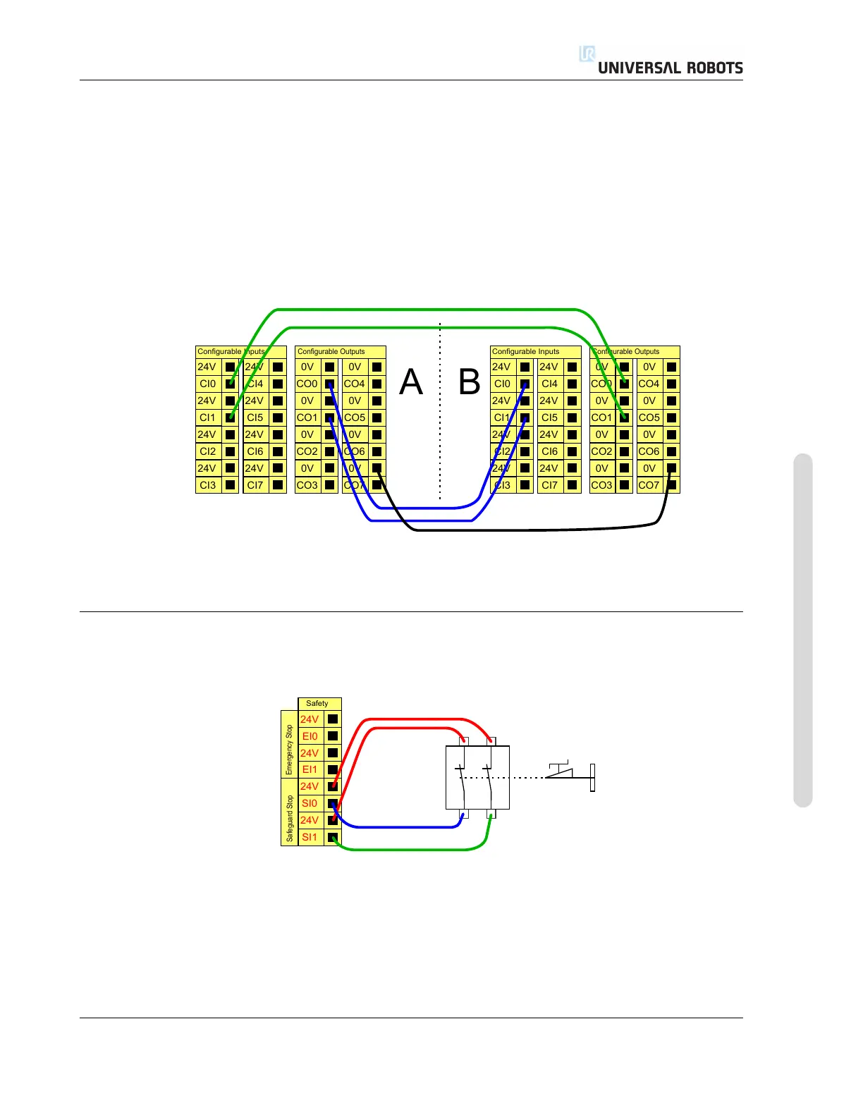
Configurable input pair: External emergency stop.
Configurable output pair: System emergency stop.
The illustration below shows how two UR robots share their emergency stop functions. In this
example the configured I/Os used are “CI0-CI1” and “CO0-CO1”.
24V
CI1
24V
CI2
24V
CI3
24V
CI0
Configurable Inputs
24V
CI5
24V
CI6
24V
CI7
24V
CI4
0V
CO1
0V
CO2
0V
CO3
0V
CO0
Configurable Outputs
0V
CO5
0V
CO6
0V
CO7
0V
CO4
24V
CI1
24V
CI2
24V
CI3
24V
CI0
Configurable Inputs
24V
CI5
24V
CI6
24V
CI7
24V
CI4
0V
CO1
0V
CO2
0V
CO3
0V
CO0
Configurable Outputs
0V
CO5
0V
CO6
0V
CO7
0V
CO4
A
B
If more than two UR robots or other machines need to be connected, a safety PLC is needed to
control the emergency stop signals.
5.3.2.4 Safeguard stop with automatic resume
An example of a basic safeguard stop device is a door switch where the robot is stopped when a
door is opened, see illustration below.
24V
EI1
24V
SI0
24V
SI1
24V
EI0
Safety
Safeguard Stop
Emergency Stop
This configuration is only intended for application where the operator cannot pass the door and
close it behind him. The configurable I/O can be used to setup a reset button outside the door, to
reactivate robot motion.
Another example where automatic resume can be appropriate is when using a safety mat or a
safety-related laser scanner, see below.
Version 3.10
Copyright © 2009–2019 by Universal Robots A/S. All rights reserved.
I-35 UR3/CB3

Table of Contents

Question and Answer IconNeed help?

Do you have a question about the Universal Robots UR3/CB3 and is the answer not in the manual?

Universal Robots UR3/CB3 Specifications

General IconGeneral
Payload3 kg
Reach500 mm
Degrees of Freedom6
IP RatingIP54
Repeatability±0.1 mm
Power Supply100-240 VAC, 50-60 Hz
Protection ClassIP54
Weight11 kg
Base Footprint128 mm diameter
Max Speed1 m/s
Programming MethodGraphical programming interface
Communication InterfaceEthernet
Safety StandardsEN ISO 10218-1
Operating Voltage24 VDC

Summary

Part I Hardware Installation Manual

1 Safety

Essential safety information for robot installation and operation.

2 Safety-related Functions and Interfaces

Built-in safety functions and electrical interfaces for safe operation.

3 Transportation

Guidelines for safely transporting the robot arm and control box.

4 Mechanical Interface

Details on robot arm mounting, workspace, and payload specifications.

5 Electrical Interface

Information on controller I/O, tool I/O, Ethernet, mains, and robot connections.

6 Maintenance and Repair

Procedures and safety instructions for robot maintenance and repair tasks.

7 Disposal and Environment

Guidelines for robot disposal and environmental regulations compliance.

8 Certifications

Presentation of product certificates and declarations from test institutes.

9 Warranties

Manufacturer's warranty conditions and disclaimer information.

A Stopping Time and Stopping Distance

Data on robot stopping times and distances for safety analysis.

B Declarations and Certificates

EU Declaration of Incorporation and various third-party certificates.

C Applied Standards

Relevant standards applied during the development of the robot.

D Technical Specifications

Detailed technical specifications for the UR robot.

E Safety Functions Tables

Tables detailing safety functions, limits, and performance levels.

Part II PolyScope Manual

10 Safety Configuration

Configuration of robot safety system settings for workspace and personnel safety.

11 Begin programming

Guide to getting started with robot programming using PolyScope.

12 On-screen Editors

Overview of PolyScope's Expression Editor and Pose Editor screens.

13 Robot Control

Controlling robot movement via Move, I/O, MODBUS, and AutoMove tabs.

14 Programming

Detailed guide on creating and editing robot programs in PolyScope.

15 Setup Screen

Interface for initializing, updating, and configuring robot settings.

Part III EUROMAP 67 Interface

16 Introduction

Introduction to the EUROMAP 67 interface for IMM integration.

17 Robot and IMM integration

Information on integrating robots with Injection Moulding Machines (IMM).

18 GUI

Controlling the EUROMAP 67 interface through the GUI.

19 Installing and uninstalling the interface

Procedures for installing and uninstalling the EUROMAP 67 interface.

20 Electrical characteristics

Electrical characteristics of MAF light guard and I/O signals for IMM integration.

Related product manuals