5.3 Controller I/O
DANGER:
1. Never connect safety signals to a PLC which is not a safety PLC
with the correct safety level. Failure to follow this warning
could result in serious injury or death as the safety functions
could be overridden. It is important to keep safety interface sig-
nals separated from the normal I/O interface signals.
2. All safety-related I/O are constructed redundantly (Two inde-
pendent channels). Keep the two channels separate so that a
single fault cannot lead to loss of the safety function.
3. Safety functions must be verified before putting the robot into
operation. Safety functions must be tested regularly.
4. The robot installation shall conform to these specifications. Fail-
ure to do so could result in serious injury or death as the safety
function could be overridden.
5.3.2.1 Default safety configuration
The robot is shipped with a default configuration which enables operation without any additional
safety equipment, see illustration below.
24V
EI1
24V
SI0
24V
SI1
24V
EI0
Safety
Safeguard Stop
Emergency Stop
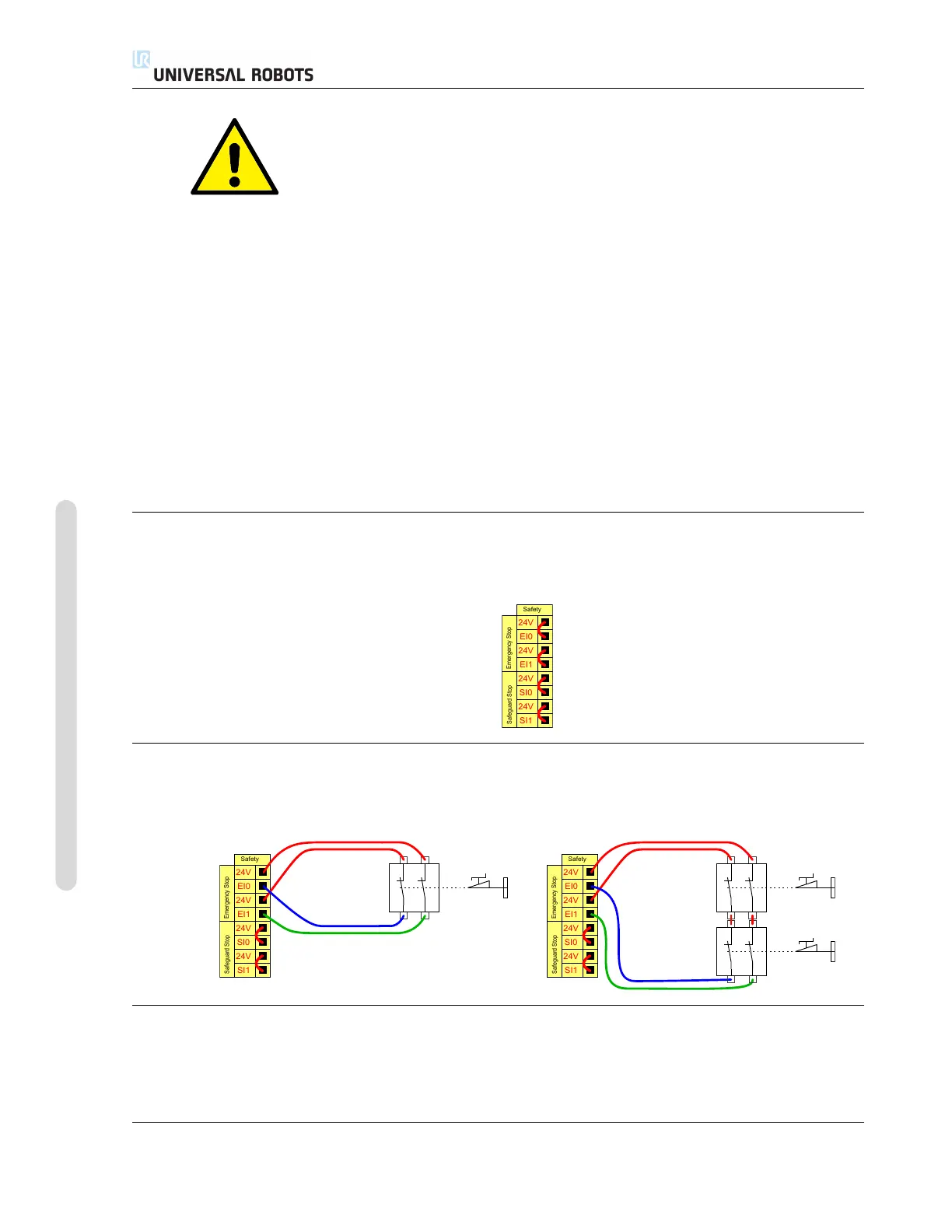
5.3.2.2 Connecting emergency stop buttons
In most applications it is required to use one or more extra emergency stop buttons. The illustration
below shows how one or more emergency stop buttons can be connected.
24V
EI1
24V
SI0
24V
SI1
24V
EI0
Safety
Safeguard Stop
Emergency Stop
24V
EI1
24V
SI0
24V
SI1
24V
EI0
Safety
Safeguard Stop
Emergency Stop
5.3.2.3 Sharing emergency stop with other machines
It is often desired to set up a common emergency stop circuit when the robot is used together with
other machines. By doing so, the operator does not need to think about which emergency stop
buttons to use.
UR3/CB3 I-34 Version 3.10
Copyright © 2009–2019 by Universal Robots A/S. All rights reserved.

 Loading...


