5.3 Controller I/O
NOTE:
All voltages and currents are in DC (Direct Current) unless otherwise
specified.
5.3 Controller I/O
This chapter explains how to connect equipment to I/O inside the control box. This I/O is ex-
tremely flexible and can be used for wide range of different equipment; including pneumatic relays,
PLCs and emergency stop buttons.
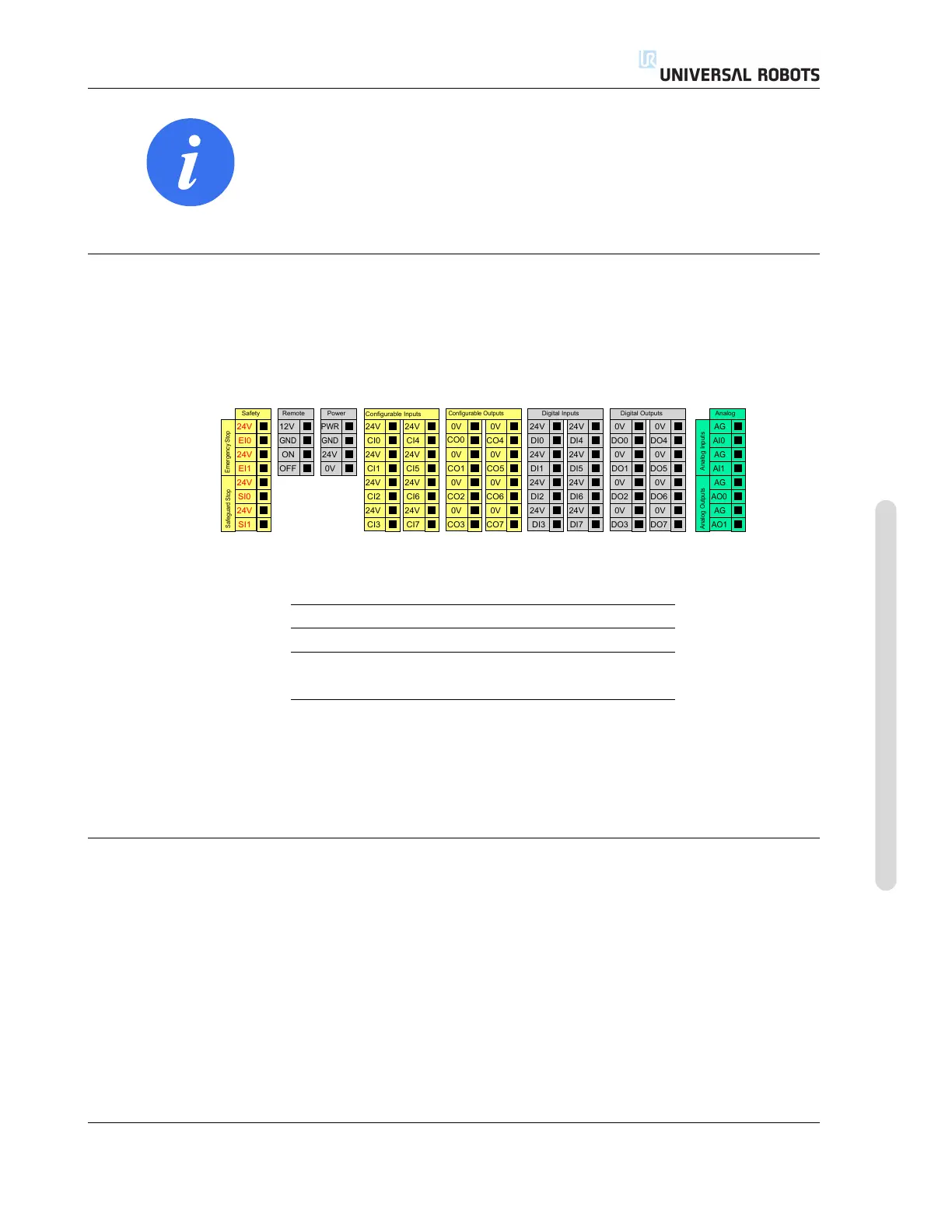
The illustration below shows the layout of electrical interface inside the control box.
24V
EI1
24V
SI0
24V
SI1
24V
EI0
Safety
ON
OFF
12V
Remote
24V
0V
PWR
GND
Power
24V
CI1
24V
CI2
24V
CI3
24V
CI0
Configurable Inputs
24V
CI5
24V
CI6
24V
CI7
24V
CI4
0V
CO1
0V
CO2
0V
CO3
0V
CO0
Configurable Outputs
0V
CO5
0V
CO6
0V
CO7
0V
CO4
24V
DI1
24V
DI2
24V
DI3
24V
DI0
Digital Inputs
24V
DI5
24V
DI6
24V
DI7
24V
DI4
0V
DO1
0V
DO2
0V
DO3
0V
DO0
Digital Outputs
0V
DO5
0V
DO6
0V
DO7
0V
DO4
AG
AI1
AG
AO0
AG
AO1
AG
AI0
Analog
Analog Outputs
Analog Inputs
Safeguard Stop
Emergency Stop
GND
The meaning of the different colors must be observed, see below.
Yellow with red text Dedicated safety signals
Yellow with black text Configurable for safety
Gray with black text General purpose digital I/O
Green with black text General purpose analog I/O
The configurable I/O can be configured as either safety-related I/O or general purpose I/O in the
GUI. See more in part II.
How to use the digital I/O is described in the following subsections. The section describing the
common specifications must be observed.
5.3.1 Common specifications for all digital I/O
This section define electrical specifications for the following 24V digital I/O of the control box.
• Safety I/O.
• Configurable I/O.
• General purpose I/O.
It is very important that UR robots are installed according the electrical specifications, which are
the same for all three different kinds of inputs.
It is possible to power the digital I/O from an internal 24V power supply or from an external power
source by configuring the terminal block called Power. This block consists of four terminals. The
Version 3.10
Copyright © 2009–2019 by Universal Robots A/S. All rights reserved.
I-31 UR3/CB3

 Loading...


