EasyManua.ls Logo

Universal Robots UR3/CB3 User Manual

Universal Robots UR3/CB3
256 pages
To Next Page IconTo Next Page
To Previous Page IconTo Previous Page
Page #182 background imageLoading...
Page #182 background image
14.9 Command: Direction
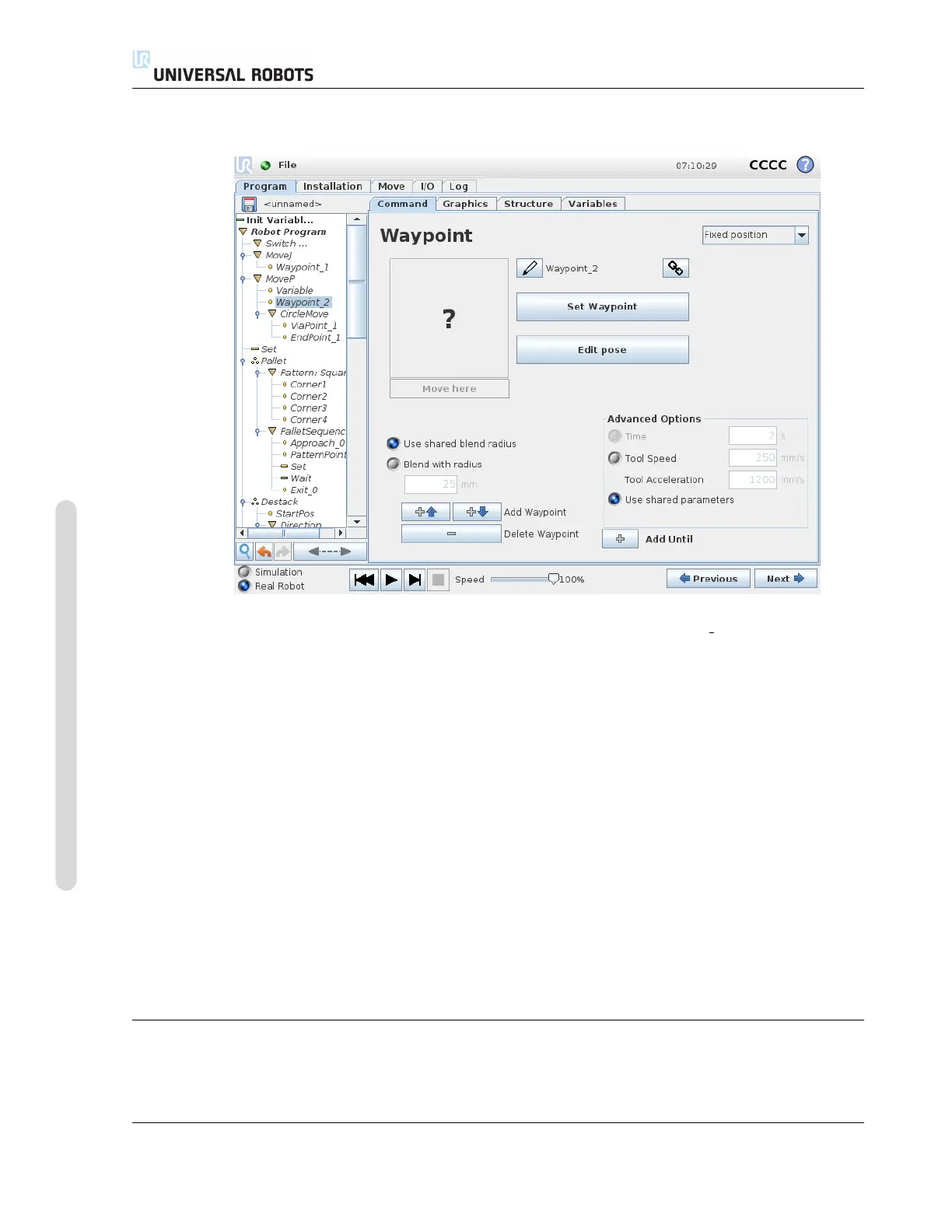
14.8 Command: Variable Waypoint
A waypoint with the position given by a variable, in this case calculated pos. The variable has
to be a pose such as
var=p[0.5,0.0,0.0,3.14,0.0,0.0]. The first three are x,y,z and the last three are the orien-
tation given as a rotation vector given by the vector rx,ry,rz. The length of the axis is the angle to be
rotated in radians, and the vector itself gives the axis about which to rotate. The position is always
given in relation to a reference frame or coordinate system, defined by the selected feature. If a
blend radius is set on a fixed waypoint and the waypoints preceding and succeeding it are variable
or if the blend radius is set on a variable waypoint, then the blend radius will not be checked for
overlap (see 14.6). If, when running the program, the blend radius overlaps a point, the robot
will ignore it and move to the next one.
For example, to move the robot 20 mm along the z-axis of the tool:
var_1=p[0,0,0.02,0,0,0]
Movel
Waypoint_1 (variable position):
Use variable=var_1, Feature=Tool
14.9 Command: Direction
The program node Direction specifies a motion relative to feature axes or TCPs. The robot moves
in along the path specified by the Direction Program Node until that movement is stopped by an
CB3 II-84 Version 3.10
Copyright © 2009–2019 by Universal Robots A/S. All rights reserved.

Table of Contents

Question and Answer IconNeed help?

Do you have a question about the Universal Robots UR3/CB3 and is the answer not in the manual?

Universal Robots UR3/CB3 Specifications

General IconGeneral
Payload3 kg
Reach500 mm
Degrees of Freedom6
IP RatingIP54
Repeatability±0.1 mm
Power Supply100-240 VAC, 50-60 Hz
Protection ClassIP54
Weight11 kg
Base Footprint128 mm diameter
Max Speed1 m/s
Programming MethodGraphical programming interface
Communication InterfaceEthernet
Safety StandardsEN ISO 10218-1
Operating Voltage24 VDC

Summary

Part I Hardware Installation Manual

1 Safety

Essential safety information for robot installation and operation.

2 Safety-related Functions and Interfaces

Built-in safety functions and electrical interfaces for safe operation.

3 Transportation

Guidelines for safely transporting the robot arm and control box.

4 Mechanical Interface

Details on robot arm mounting, workspace, and payload specifications.

5 Electrical Interface

Information on controller I/O, tool I/O, Ethernet, mains, and robot connections.

6 Maintenance and Repair

Procedures and safety instructions for robot maintenance and repair tasks.

7 Disposal and Environment

Guidelines for robot disposal and environmental regulations compliance.

8 Certifications

Presentation of product certificates and declarations from test institutes.

9 Warranties

Manufacturer's warranty conditions and disclaimer information.

A Stopping Time and Stopping Distance

Data on robot stopping times and distances for safety analysis.

B Declarations and Certificates

EU Declaration of Incorporation and various third-party certificates.

C Applied Standards

Relevant standards applied during the development of the robot.

D Technical Specifications

Detailed technical specifications for the UR robot.

E Safety Functions Tables

Tables detailing safety functions, limits, and performance levels.

Part II PolyScope Manual

10 Safety Configuration

Configuration of robot safety system settings for workspace and personnel safety.

11 Begin programming

Guide to getting started with robot programming using PolyScope.

12 On-screen Editors

Overview of PolyScope's Expression Editor and Pose Editor screens.

13 Robot Control

Controlling robot movement via Move, I/O, MODBUS, and AutoMove tabs.

14 Programming

Detailed guide on creating and editing robot programs in PolyScope.

15 Setup Screen

Interface for initializing, updating, and configuring robot settings.

Part III EUROMAP 67 Interface

16 Introduction

Introduction to the EUROMAP 67 interface for IMM integration.

17 Robot and IMM integration

Information on integrating robots with Injection Moulding Machines (IMM).

18 GUI

Controlling the EUROMAP 67 interface through the GUI.

19 Installing and uninstalling the interface

Procedures for installing and uninstalling the EUROMAP 67 interface.

20 Electrical characteristics

Electrical characteristics of MAF light guard and I/O signals for IMM integration.

Related product manuals