EasyManua.ls Logo

Universal Robots UR3/CB3 User Manual

Universal Robots UR3/CB3
256 pages
To Next Page IconTo Next Page
To Previous Page IconTo Previous Page
Page #178 background imageLoading...
Page #178 background image
14.6 Command: Fixed Waypoint
evaluated before we actually reach WP 2 which is somewhat counter-intuitive when looking at the
program sequence. If a waypoint is a stop point and followed by conditional expressions to deter-
mine the next waypoint (e.g. the I/O command) it is executed when the robot arm has stopped at
the waypoint.
MoveL
WP_I
WP_1 (blend)
WP_2 (blend)
if (digital_input[1]) then
WP_F_1
else
WP_F_2
WP_I
WP_1
WP_2
WP_F_1
WP_F_2
*
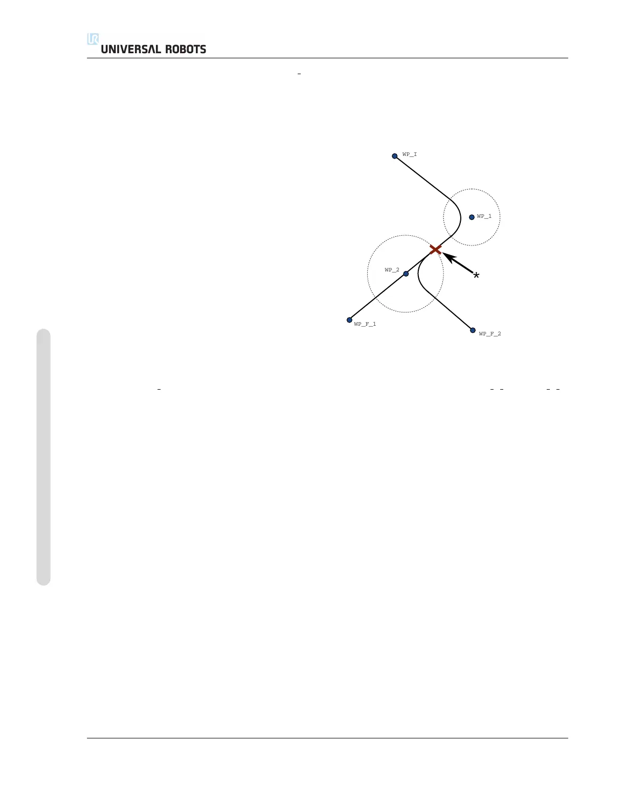
Figure 14.5: WP I is the initial waypoint and there are two potential final waypoints WP F 1 and WP F 2,
depending on a conditional expression. The conditional if expression is evaluated when the robot arm
enters the second blend (*).
Trajectory type combinations It is possible to blend between all four combinations of trajectory
types of MoveJ and MoveL, but the specific combination will affect the computed blend trajectory.
There are 4 possible combinations:
1. MoveJ to MoveJ (Pure Joint space blend)
2. MoveJ to MoveL
3. MoveL to MoveL (Pure Cartesian space blend)
4. MoveL to MoveJ
Pure joint space blending (bullet 1) vs. pure Cartesian space blending (bullet 3) is compared in
figure 14.6. It shows two potential paths of the tool for identical sets of waypoints.
Of the different combinations, bullets 2, 3 and 4 will result in trajectories that keep within the
boundaries of the original trajectory in Cartesian space. An example of a blend between different
trajectory types (bullet 2) can be seen in figure 14.7.
Pure joint space blends (bullet 1), however, may behave in a way that is less intuitive, since the
robot will try to achieve the smoothest possible trajectory in Joint space taking velocities and time
requirements into account. Due to this, they may deviate from the course specified by the way-
points. This is especially the case if there are significant differences in a joint’s velocity between the
CB3 II-80 Version 3.10
Copyright © 2009–2019 by Universal Robots A/S. All rights reserved.

Table of Contents

Question and Answer IconNeed help?

Do you have a question about the Universal Robots UR3/CB3 and is the answer not in the manual?

Universal Robots UR3/CB3 Specifications

General IconGeneral
Payload3 kg
Reach500 mm
Degrees of Freedom6
IP RatingIP54
Repeatability±0.1 mm
Power Supply100-240 VAC, 50-60 Hz
Protection ClassIP54
Weight11 kg
Base Footprint128 mm diameter
Max Speed1 m/s
Programming MethodGraphical programming interface
Communication InterfaceEthernet
Safety StandardsEN ISO 10218-1
Operating Voltage24 VDC

Summary

Part I Hardware Installation Manual

1 Safety

Essential safety information for robot installation and operation.

2 Safety-related Functions and Interfaces

Built-in safety functions and electrical interfaces for safe operation.

3 Transportation

Guidelines for safely transporting the robot arm and control box.

4 Mechanical Interface

Details on robot arm mounting, workspace, and payload specifications.

5 Electrical Interface

Information on controller I/O, tool I/O, Ethernet, mains, and robot connections.

6 Maintenance and Repair

Procedures and safety instructions for robot maintenance and repair tasks.

7 Disposal and Environment

Guidelines for robot disposal and environmental regulations compliance.

8 Certifications

Presentation of product certificates and declarations from test institutes.

9 Warranties

Manufacturer's warranty conditions and disclaimer information.

A Stopping Time and Stopping Distance

Data on robot stopping times and distances for safety analysis.

B Declarations and Certificates

EU Declaration of Incorporation and various third-party certificates.

C Applied Standards

Relevant standards applied during the development of the robot.

D Technical Specifications

Detailed technical specifications for the UR robot.

E Safety Functions Tables

Tables detailing safety functions, limits, and performance levels.

Part II PolyScope Manual

10 Safety Configuration

Configuration of robot safety system settings for workspace and personnel safety.

11 Begin programming

Guide to getting started with robot programming using PolyScope.

12 On-screen Editors

Overview of PolyScope's Expression Editor and Pose Editor screens.

13 Robot Control

Controlling robot movement via Move, I/O, MODBUS, and AutoMove tabs.

14 Programming

Detailed guide on creating and editing robot programs in PolyScope.

15 Setup Screen

Interface for initializing, updating, and configuring robot settings.

Part III EUROMAP 67 Interface

16 Introduction

Introduction to the EUROMAP 67 interface for IMM integration.

17 Robot and IMM integration

Information on integrating robots with Injection Moulding Machines (IMM).

18 GUI

Controlling the EUROMAP 67 interface through the GUI.

19 Installing and uninstalling the interface

Procedures for installing and uninstalling the EUROMAP 67 interface.

20 Electrical characteristics

Electrical characteristics of MAF light guard and I/O signals for IMM integration.

Related product manuals