10.12 Boundaries
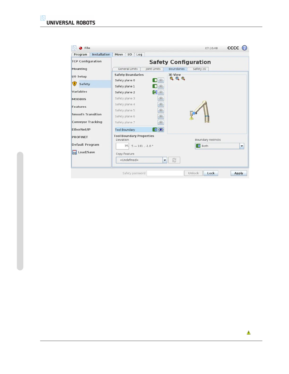
10.12.4 Tool Boundary configuration
The Tool Boundary Properties panel at the bottom of the tab defines a limit on the orientation
of robot tool composed of a desired tool orientation and a value for the maximum allowed deviation
from this orientation.
Deviation The Deviation text field shows the value for the maximum allowed deviation of the
orientation of the robot tool from the desired orientation. Modify this value by tapping the text
field and entering the new value.
The accepted value range together with the tolerance and unit of the deviation are listed next to the
text field.
Copy Feature The desired orientation of the robot tool is specified using a feature (see 13.12)
from the current robot installation. The z-axis of the selected feature will be used as the desired tool
orientation vector for this limit.
Use the drop down box in the lower left portion of the Tool Boundary Properties panel to
select a feature. Only the point and plane type features are available. Choosing the <Undefined>
item clears the configuration of the plane.
It should be noted that when the limit has been configured by selecting a feature, the orientation
information is only copied to the limit; the limit is not linked to that feature. This means that if there
are changes to the position and orientation of a feature, which has been used to configure the limit,
the limit is not automatically updated. If the feature has changed, this is indicated by a icon
CB3 II-18 Version 3.10
Copyright © 2009–2019 by Universal Robots A/S. All rights reserved.

 Loading...


