5.4 Tool I/O
Parameter Min Typ Max Unit
Voltage when open -0.5 - 26 V
Voltage when sinking 1A - 0.05 0.20 V
Current when sinking 0 - 600 mA
Current through GND 0 - 600 mA
An example of how to use a digital output is shown in the following subsection.
CAUTION:
1. The digital outputs in the tool are not current limited and over-
riding the specified data can cause permanent damage.
5.4.1.1 Using the Tool Digital Outputs
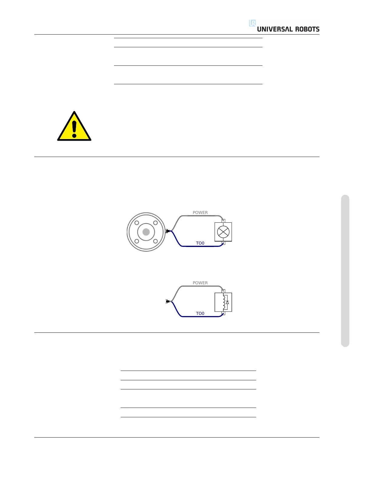
The example below illustrates how to turn on a load, when using the internal 12V or 24V power
supply. Remember that you have to define the output voltage at the I/O tab. Keep in mind that
there is voltage between the POWER connection and the shield/ground, even when the load is
turned off.
Note: It is highly recommended to use a protective diode for inductive loads, as shown below.
5.4.2 Tool Digital Inputs
The digital inputs are implemented as PNP with weak pull-down resistors. This means that a
floating input will always read low. The electrical specifications are shown below.
Parameter Min Typ Max Unit
Input voltage -0.5 - 26 V
Logical low voltage - - 2.0 V
Logical high voltage 5.5 - - V
Input resistance - 47k - Ω
An example of how to use a digital input is shown in the following subsection.
Version 3.10
Copyright © 2009–2019 by Universal Robots A/S. All rights reserved.
I-43 UR3/CB3

 Loading...


