NOTE:
STEPS
3
A
AND
2
8:
Maintain the
location
of
the cleaner blade from
Figure
5.
It is acceptable for the blade
seal assembly and retainer to extend
over the end of the extrusion.
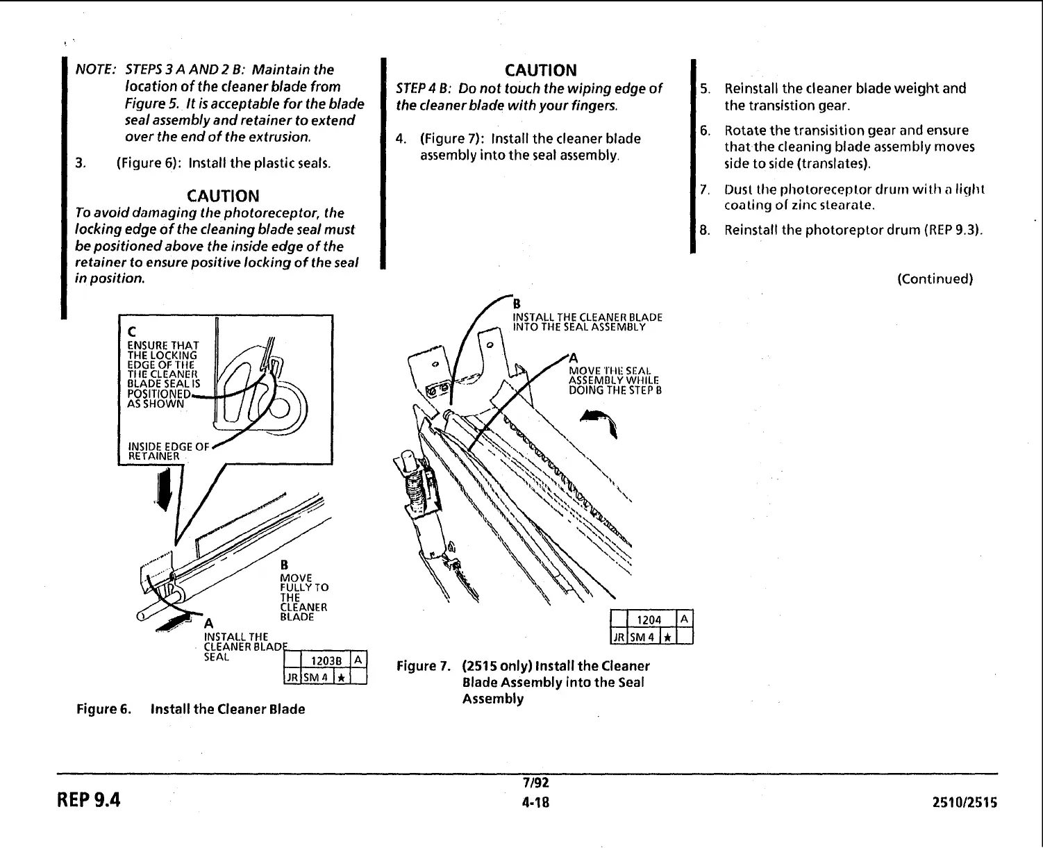
3.
(Figure
6):
lnstall the plastic seals.
CAUTION
To
avoid damaging the photoreceptor, the
locking edge of the cleaning blade seal must
be positioned above the inside edge of the
retainer to ensure positive locking of the seal
in
position.
INSIDE EDGE
OF
RETAINER
FULLY
TO
CLEANER
INSTALL THE
CLEANER BLAD
SEAL
Figure
6.
Install the Cleaner Blade
CAUTION
STEP4
6: Do not touch the wiping edge
of
the cleaner blade with
your
fingers.
4.
(Figure
7):
lnstall the cleaner blade
assembly into the seal assembly.
INSTALL THE CLEANER BLADE
INTO THE SEAL ASSEMBLY
Figure
7.
(2515
only) Install the Cleaner
Blade Assembly into the Seal
Assembly
5.
Reinstall the cleaner blade weight and
the transistion gear.
6.
Rotate the transisition gear and ensure
that the cleaning blade assembly moves
side
to
side (translates).
7.
Dust the photoreceplor
drurn
with
n
light
coaling
of
zinc stearale.
8.
Reinstall the photoreptor drum (REP
9.3).
(Continued)
REP
9.4
 Loading...