Rockwell Automation Publication 2711P-UM006A-EN-P - November 2010 101
Chapter
6
Install and Replace Components
Chapter Objectives
This chapter shows provides topics on how to install or replace components of
the PanelView Plus 6 terminals.
Required Tools
These tools are required to install and replace components:
• #00, #1, and #2 Phillips screwdriver
• Electrostatic Discharge (ESD) wristband
Precautions
Before installing or replacing any components, disconnect power from the
terminal. During installation, take care not to touch any of the exposed electronic
components.
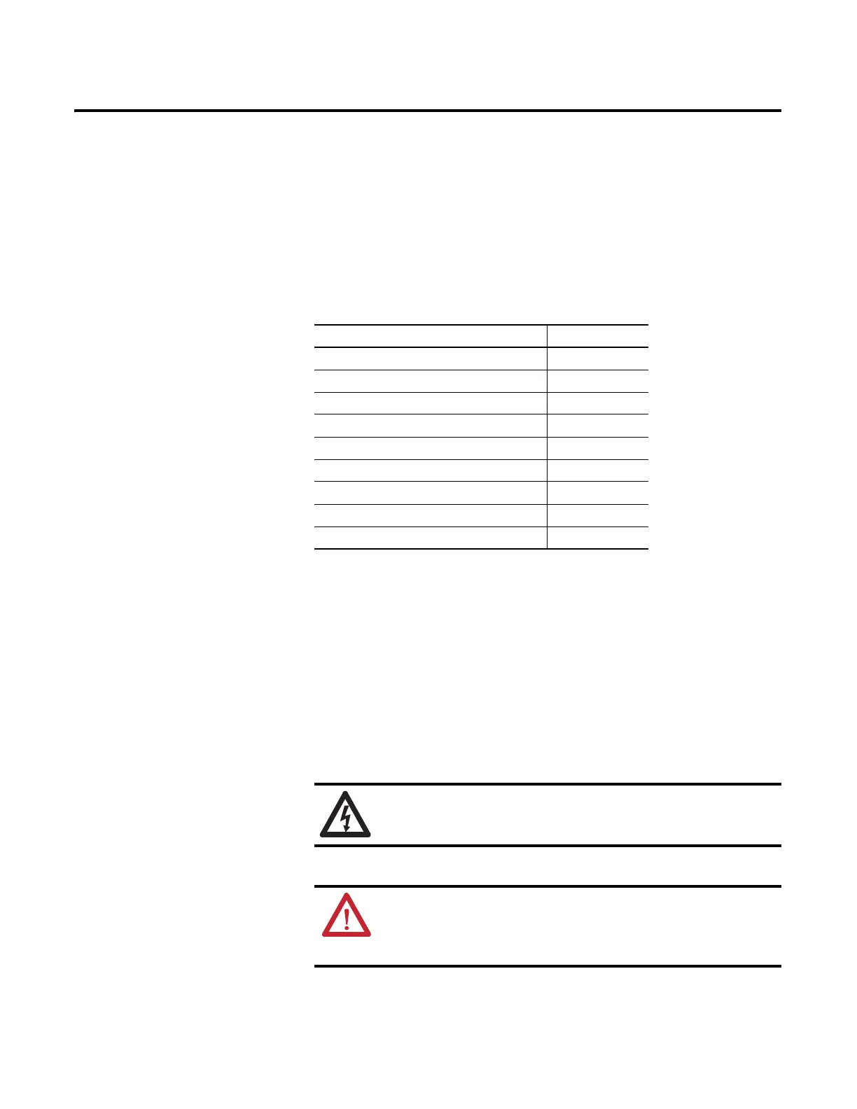
Topic Page
Install or Replace the Logic Module 102
Install or Replace a Communication Module 103
Replace the Display Module 105
Replace the Bezel 106
Replace the Battery 109
Replace the Backlight 111
Remove the Product ID Label 114
Load an SD Card or USB Flash Drive 115
Clean the Display 116
SHOCK HAZARD: Disconnect all power from the terminal before
installing or replacing any components. Failure to disconnect power may
result in electrical shock or damage to the terminal.
ATTENTION: Be careful when touching any of the exposed electronic
components to prevent damage from electrostatic discharge (ESD).
Work in a static free environment and wear a properly grounded ESD
wristband.
 Loading...