Rockwell Automation Publication 2711P-UM006A-EN-P - November 2010 103
Install and Replace Components Chapter 6
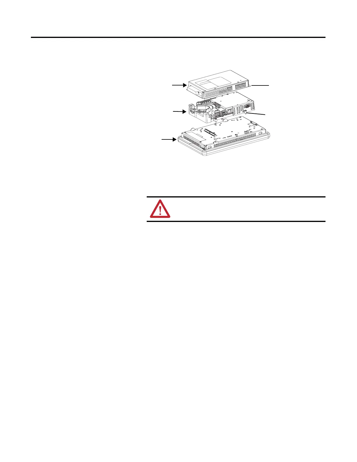
4. Remove the four screws that secure the communication module, if
attached, to the logic module and set the communication module aside.
5. Loosen the four captive screws that secure the logic module to the display
module.
6. Carefully lift the logic module from the back of the display.
7. Install the new logic module and torque the four captive screws to
0.58 N•m (5…7 lb•in)
8. Install, the communication module, if necessary, and torque the four
screws to 0.58 N•m (5…7 lb•in).
Install or Replace a
Communication Module
The communication module installs over the logic module. Communication
modules are available as separate catalog numbers for field installation.
Follow these steps to install a communication module.
1. Disconnect power from the terminal.
Communication Module
Display Module
Captive Screw
Screw
Logic Module
ATTENTION: Wear a properly grounded ESD wristband before
touching any of the electronic components in the logic module.
TIP
The logic module must be attached to the display module before you
attach the communication module.
 Loading...