124 Rockwell Automation Publication 2711P-UM006A-EN-P - November 2010
Chapter 7 Terminal Connections
Ethernet Connections
The Ethernet port on the logic module that supports these connections:
• EtherNet/IP communication
• Third-party Ethernet communication
• Auto MDI/MDIX connections
• Network connections
• Application uploads/downloads
• Printing
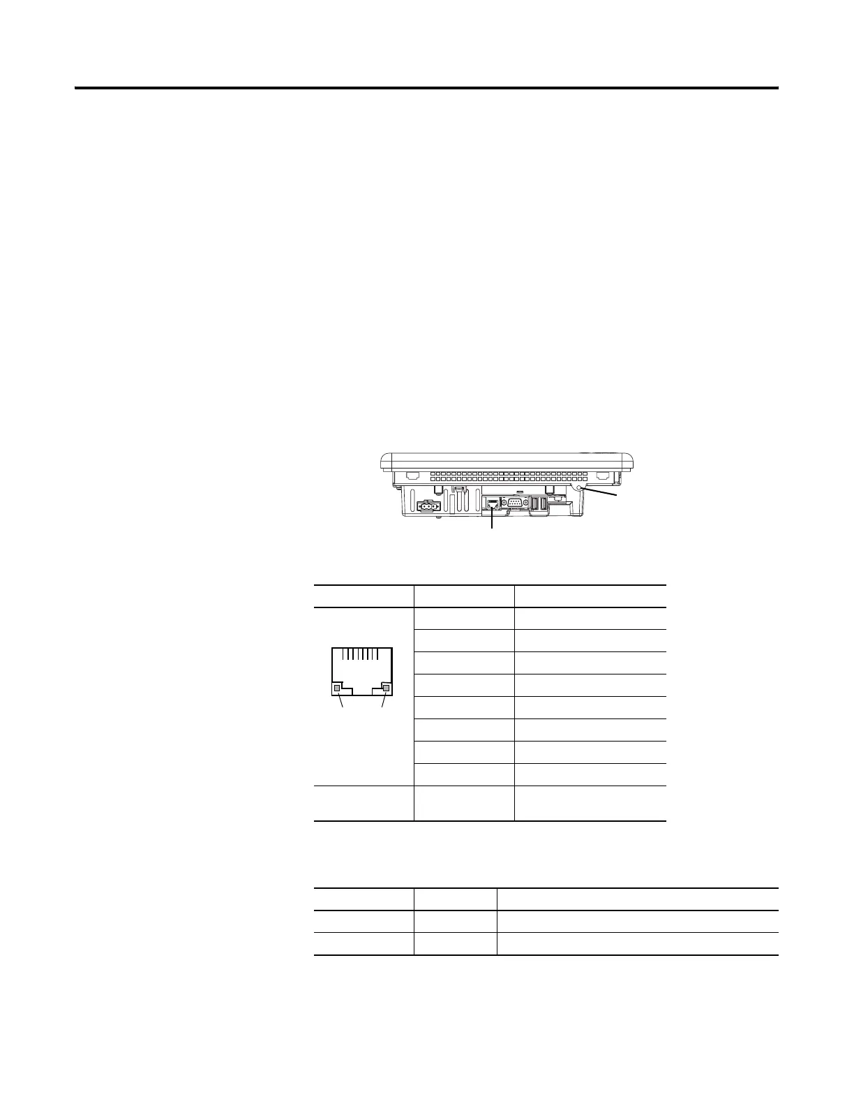
Ethernet Connector
The base-configured unit of the terminals has an RJ45,
10/100 Base-T connector for EtherNet/IP or Ethernet TCP/IP network
communication.
Figure 14 - Ethernet Connector
The Ethernet connector has two indicators that provide the status of activity.
Table 53 - Ethernet Connector Pinout
Connector Pin Pin Name
Looking into RJ45
Connector
1TD+
2TD-
3RD+
4NC
5NC
6RD-
7NC
8NC
Shield Connection No direct connection
(AC coupled to chassis GND)
Table 54 - Ethernet Status Indicators
Indicator LED Color Description
Link Integrity Yellow Asserted when a link is present.
Activity LED Green Pulsed active when receive or transmit activity is present.
Ethernet Port
Insert plastic tie wrap in
hole and use as strain relief
for all attached cables.
1
Yellow
LED
Green
LED
 Loading...