Advanced Opreation
Design Center
105
Design Center Stage 4 (Sew Setting Stage)
Changing Software Settings
Changing the grid settings
A grid of dotted lines or solid lines can be displayed
or hidden, and the spacing for the grid can be
adjusted. (This function is available only in stage 3
(Figure Handle stage).)
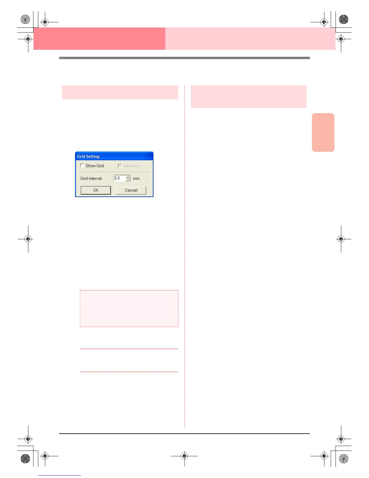
1. Click Display, then Grid Setup.
→ The Grid Setting dialog box appears.
2. To display the grid, select the Show Grid
check box.
To hide the grid, clear the Show Grid check
box.
3. To set the grid spacing, type or select a value
in the Grid interval box. (The setting range is
0.1 to 25.4 mm (0.004 to 1.0 inch).)
4. To display the grid as solid lines, select the
with Axes check box.
To display the grid as dotted lines, clear the
with Axes check box.
5. Click OK to apply the changes and to close the
dialog box.
b Memo:
To close the dialog box without applying the
changes to the grid, click
Cancel
.
Changing the measurement
units
The measurements for values displayed in the
application can be in either millimeters or inches.
1. Click Option, then Select System Unit, and
then select the desired measurement units
(mm or inch).
a Note:
When the
Show Grid
check box is selected
and the
with Axes
check box is cleared,
only the intersecting points of the grid will be
displayed.
PeDesignV6Eng.book Page 105 Thursday, July 8, 2004 11:59 AM
 Loading...