DVP15MC11T Operation Manual
8.5.4 GE
FB/FC Explanation
FC
GE is used for a greater- than or equal comparison of two or more variables or
constants.
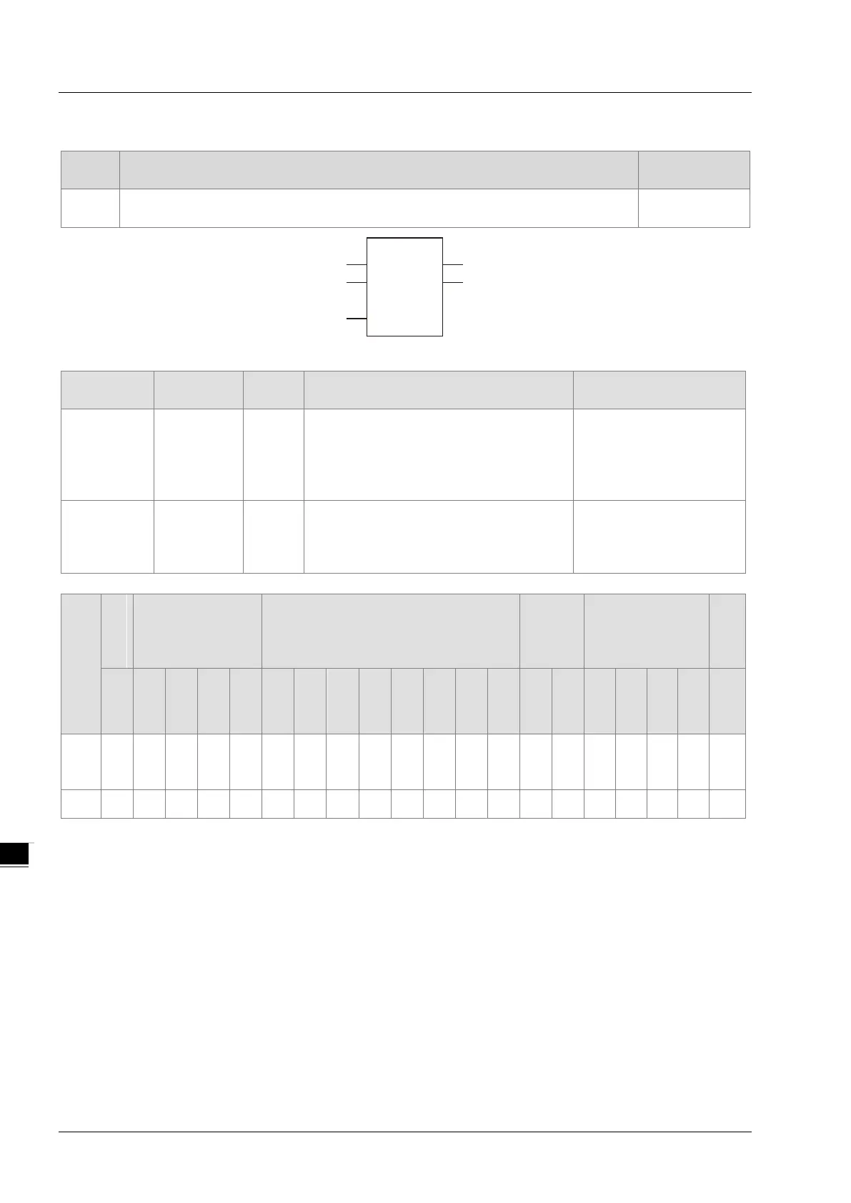
DVP15MC11T
Parameters
Meaning
Description Valid range
In1 to InN
Comparison
data
Input
The number of comparison data can be
increased or decreased through the
programming software. Maximum: 8.
Minimum: 2. That is N=2 ~ 8.
Depends on
of the variable that the
input parameter is
connected to.
Out
Comparison
result
Output Comparison result
of the variable that the
output parameter is
Boolean
Bit string Integer
Real
number
Time, date
String
BOOL
BYTE
WORD
DWORD
LWORD
USINT
UINT
UDINT
ULINT
SINT
INT
DINT
LINT
REAL
LREAL
TIME
DATE
TOD
DT
STRING
to
● ● ● ● ● ● ● ● ● ● ● ● ● ● ● ● ● ● ● ●
Out
●
Note:
The symbol ● indicates that the parameter is allowed to connect to the variable or constant of the data type.
Function Explanation
GE is used for a greater than or equal comparison of two or more variables or constants. if In1 ≥ In2
≥
… ≥ InN, Out is TRUE. Otherwise, Out is FALSE.
The input parameters In1~InN are allowed to be the variables of different data types in this
instruction when the data types of input variables are not BOOL, TIME, DATE, TOD and STRING.
When the data type of one input variable is one of BOOL, TIME, DATE, TOD and STRING, input
parameters In1~InN are all required to be of the data type. For example, if the data type of In1 is
TIME, the data type of In2~InN must be TIME. Otherwise, an error will occur in the compiling of the
software.
8-34