Chapter 8 Logic Instructions
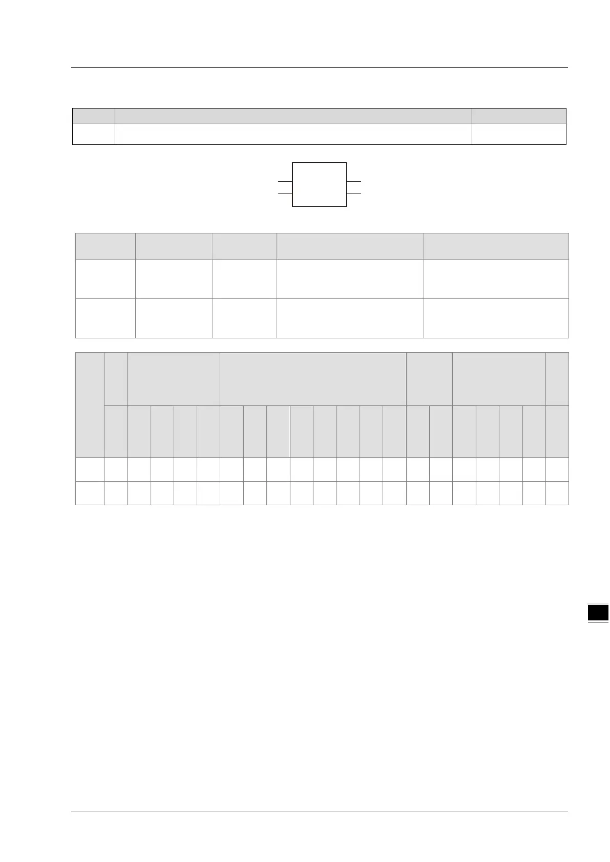
8.8.11 RadToDeg
FC
DegToRad is used to convert radians to degrees.
DVP15MC11T
Parameters
Meaning
Description Valid range
In Radians Input Radians to convert
Depends on the data type of
the variable that the input
parameter is connected to.
Out Degrees Output
Degrees converted from
radians
Depends on the data type of
the variable that the output
parameter is connected to.
Boolean
Bit string Integer
Real
number
Time, date
String
BOOL
BYTE
WORD
DWORD
LWORD
USINT
UINT
UDINT
ULINT
SINT
INT
DINT
LINT
REAL
LREAL
TIME
DATE
TOD
DT
STRING
In
● ● ● ● ● ● ● ● ● ● ● ● ● ●
Out
●
Note:
The symbol ● indicates that the parameter is allowed to connect to the variable or constant of the data type.
Function Explanation
RadToDeg is used to convert the input parameter In to degrees and the result is output to Out. That
is, Out =( In/π)* 180.
The units of In and Out are radian and degree (°) respectively.
Users can choose different data types for the input parameter in this instruction. But the data type of
the output parameter is restricted to LREAL. An error will occur during the compiling of the software
if the data type of the output parameter is not LREAL.
Precautions for Correct Use
The input variable is not allowed to omit. An error will occur during the compiling of the software if
the input variable is omitted. But the output variable is allowed to omit.
Programming Example
The data types of variables RadToDeg _In and Out1 are INT and LREAL respectively. The value of
Out1 is 572. 957795130824 if the value of RadToDeg _In is 10 when RadToDeg _EN changes to
TRUE. The value of Out1 is -572. 957795130824 as RadToDeg _In is -10.
8-77