DVP15MC11T Operation Manual
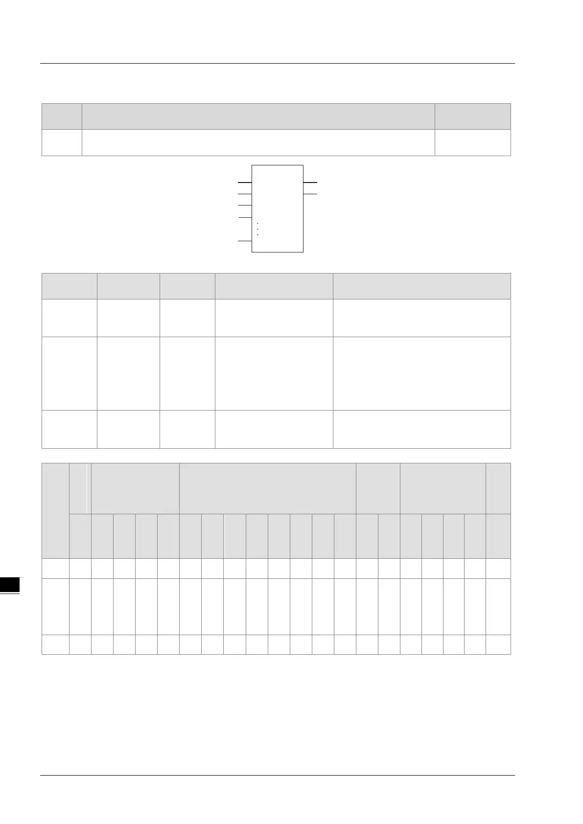
8.11.4 MUX
FB/FC
Explanation
FC
MUX is used for selecting one of two or more variables or constants and the
result is output to Out.
DVP15MC11T
Parameters
Meaning
Description Valid range
K Gate Input Gate
Depends on the data type of the
variable that the input parameter is
In0, In1 to
InN
Selections Input
The selections can be
added or removed while
the program is being
written. The maximum
number of selections is 8.
N=2~8.
Depends on the data type of the
variable that the input parameter is
connected to.
Out
Selection
result
Output Selection result
Depends on the data type of the
variable that the output parameter is
connected to.
Boolean
Bit string Integer
Real
number
Time, date
String
BOOL
BYTE
WORD
DWORD
LWORD
USINT
UINT
UDINT
ULINT
SINT
INT
DINT
LINT
REAL
LREAL
TIME
DATE
TOD
DT
STRING
K
●
In1
to
● ● ● ● ● ● ● ● ● ● ● ● ● ● ● ● ● ● ● ●
Out
● ● ● ● ● ● ● ● ● ● ● ● ● ● ● ● ● ● ● ●
Note:
The symbol ● indicates that the parameter is allowed to connect to the variable or constant of the data type.
Function Explanation
Based on the selection condition K, the MUX instruction selects one of In0~InN and the selection
result is output to Out. The value of Out corresponds to the value of K as shown in the following
table.
MUX
EN ENO
K Out
In1
In0
InN
.
.
.
8-138

 Loading...


