Appendix A. Modbus Communication
A.2 Message Format in RTU Mode
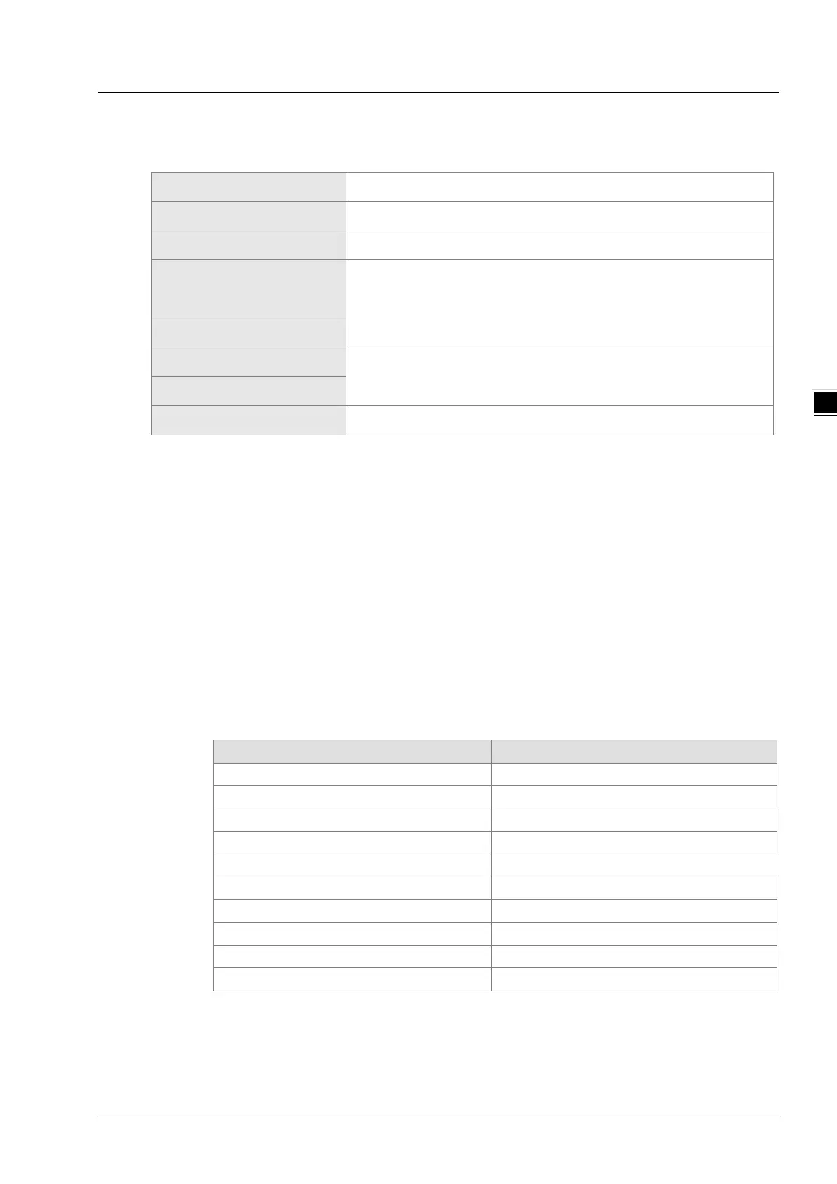
Communication data structure
Start
No input data for more than 10ms
Communication address
Slave address: 8-bit binary address
Function code
Function code: 8-bit binary address
Data (n-1)
Data content
n × 8 bit binary data, n<=202
…….
Data 0
Low byte of CRC check
CRC check sum
High byte of CRC check
End
CRC check sum is composed of two 8-bit binary data
Communication address
The range of a valid communication address is 0~254. The communication address 0 indicates
to broadcast the message to all slaves and the slaves which have received the broadcast
message do not make any response. If the communication address is not 0, slaves will reply to
master as normal. For example, to communication with the slave with the communication
address of 16, the address of the slave is set as 0x10 since decimal 16 is equal to hexadecimal
10.
Function code and data
The data format is determined by function codes.
For example, to read the data of two continuous addresses with 0x0000 as start address in
DVP15MC11T, the address of DVP15MC11T is 1, 0x0000 is the Modbus address of %MW0 in
DVP15MC11T PLC.
The data in the communication cable and the explanation on them are shown below:
PC→DVP15MC11T: “01 03 00 00 00 02 C4 0B”
DVP15MC11T→PC: “01 03 04 00 01 02 00 2A 32”
Request message:
Field name Character
Start
No input data for more than 10ms
Function code
03
High byte of Modbus address
00
Low byte of Modbus address
00
Read high byte of data number
00
Read low byte of data number
Low byte of CRC check sum
C4
High byte of CRC check sum
0B
End
No input data for more than 10ms
A-5

 Loading...


