Chapter 8 Logic Instructions
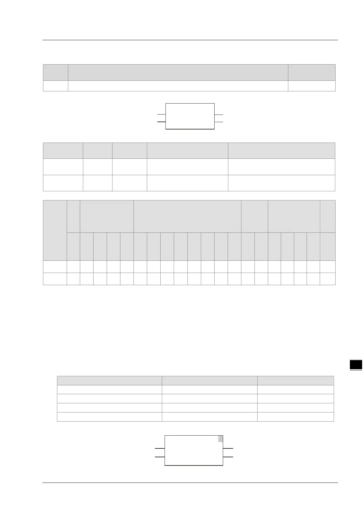
8.3.2 F_TRIG
FB/FC
Explanation
FB
F_TRIG is used for the falling edge trigger. DVP15MC11T
Parameters
Meaning
Description Valid range
CLK
Input Falling edge trigger signal TRUE or FALSE
Q
Output Output for a period TRUE or FALSE
Boolean
Bit string Integer
Real
number
Time, date
String
BOOL
BYTE
WORD
DWORD
LWORD
USINT
UINT
UDINT
ULINT
SINT
INT
DINT
LINT
REAL
LREAL
TIME
DATE
TOD
DT
STRING
CLK
●
Q
●
Note:
The symbol ● indicates that the parameter is allowed to connect to the variable or constant of the data type.
Function Explanation
When CLK of F_TRIG changes from TRUE to FALSE, Q output is TRUE for only one period. In other
circumstances, Q is FALSE.
Precautions for Correct Use
Q will have no output until the falling edge signal at CLK is detected.
Programming Example
The variable table and program
F_TRIG
EN ENO
CLK
Q
F_TRIG_instance
1
F_TRIG
EN ENO
CLK Q
F_TRG
F_TRG_EN
F_TRG_CLK
F_TRG_Q
8-9

 Loading...


