Appendix A. Modbus Communication
}
}
return reg_crc; // the value that sent back to the CRC register finally
}
A.3 Modbus
Function Codes Supported
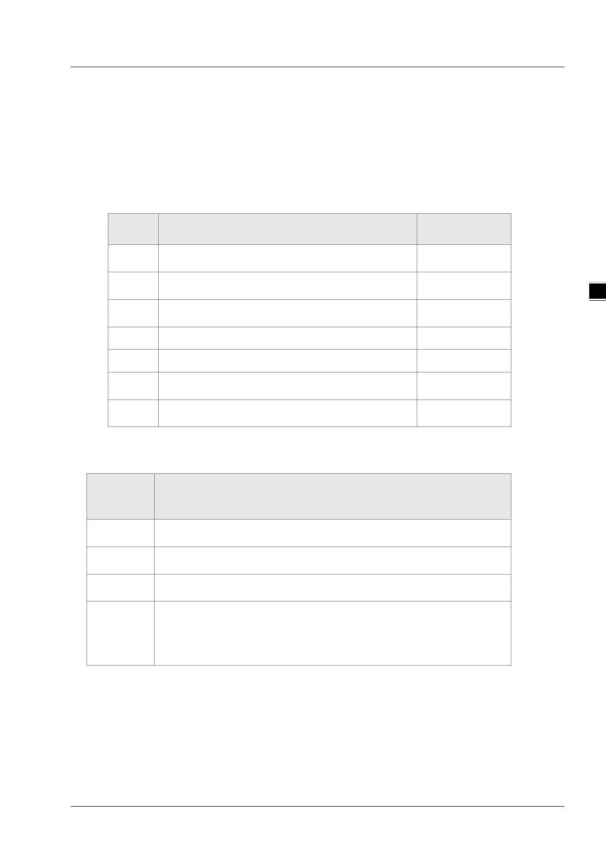
The function codes which are supported by DVP15MC11T are listed in the following table when
COM2 port is possessed by the motion control module.
Function
code
Explanation Available register
0x01
Read output bit register values; the data of 256 bits at
most can be read at a time
%QX
0x02
Read bit register values; the data of 256 bits at most
%IX,%QX
0x03
Read one single or multiple word register value; the
data of 100 words at most can be read at a time.
%MW,%QW,%IW
0x05 Write one single bit register value. %QX
0x06 Write one single word register value. %MW,%QW
0x0F
Write multiple bit register value; the data of 256 bits at
most can be written at a time.
%QX
0x10
Write multiple word register value; the data of 100
words at most can be written at a time.
%MW,%QW
A.4 Modbus Exception Response Code Supported
Exception response codes supported by DVP15MC11T are listed in the following table.
Exception
response
code
Explanation
0x01
Illegal command codes: the command codes in the command message
which PLC receives are invalid.
0x02
Illegal register address: the address in the command message received is
invalid.
0x03
Illegal register value: the data in the command message received by PLC
are invalid.
0x07
Check if the check sum is correct.
Illegal command message
Too short command message
The length of the command message exceeds the valid range.
A-7