DVP15MC11T Operation Manual
Byte NO. Name Byte
Byte8
The number of read word registers.
Single byte
Byte9
The content value in a word register
High byte
Byte10 Low byte
…
The content value in a word register
High byte
Byte n Low byte
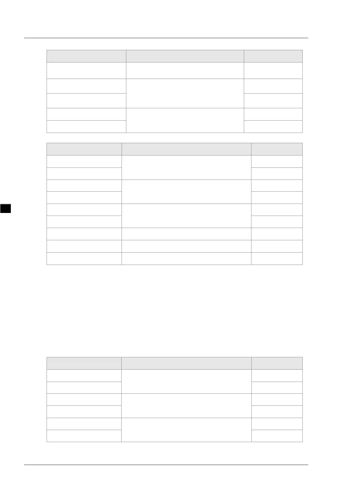
Exception response message data structure:
Byte NO. Name Byte
Byte0
Transaction identifier
High byte
Byte1
Low byte
Byte2
Protocol identifier
High byte
Byte3
Low byte
Byte4
Modbus data length
High byte
Byte5
Low byte
Byte6
Modbus ID Single byte
Byte7
0x80+ function code Single byte
Byte8
Exception response code Single byte
Example
To read the content value in the addresses 0x0000 and 0x0001 inside DVP15MC11T via
function code 03. 0x0000 and 0x0001 are the Modbus address of %MW0 and %MW1 inside
DVP15MC11T respectively. Suppose that the value of %MW0 is 0x0100 and the value
of %MW1 is 0x0200.
Request message: 00 00 00 00 00 06 01 03 00 00 00 02
Response message: 00 00 00 00 00 07 01 03 04 01 00 02 00
Function code: 06 to write one single word register value
Request message data structure:
Byte NO. Name Byte
Byte0
Transaction identifier
High byte
Byte1
Low byte
Byte2
Protocol identifier
High byte
Byte3
Low byte
Byte4
Modbus data length
High byte
Byte5
Low byte
B-4

 Loading...


