 Loading...
Do you have a question about the Furuno FV-110 and is the answer not in the manual?
Introduction and welcome message to the owner of the FV-110 system.
Highlights the main capabilities and characteristics of the FV-110 system.
Details regarding software licensing and source code availability for the FV-110.
General advisories including manual usage, copyright, and modification policies.
Guidelines for the proper disposal of the FV-110 product.
Instructions for the disposal of used batteries from FURUNO products.
Covers warnings about opening equipment, water ingress, abnormal operation, and environmental hazards.
Advisories on handling, power, grounding, voltage, antenna proximity, and compass safety.
Details limitations and restrictions related to VSAT usage in specific regions.
Lists the standard components included with the FV-110 system.
Details optional accessories and kits available for the FV-110 system.
Overview of the FV-110 stabilized maritime VSAT antenna system.
Description of the FV-110 Above Deck Unit, its components and specifications.
Details about the FV-110 Antenna Control Unit, its interfaces and functions.
Information on the VSAT Modem Unit and its compatibility with the FV-110.
Lists the type approvals for satellites supported by the FV-110 system.
Procedure for activating the FV-110 system for VSAT service.
Lists applicable FURUNO model and part numbers, and available options for the FV-110.
Instructions for unpacking the FV-110 system components.
Guidelines for preparing the installation site, considering obstructions and mounting.
Detailed steps for installing the Above Deck Unit (ADU) of the FV-110.
Instructions for installing the Antenna Control Unit (ACU) of the FV-110.
Guidance for installing the VSAT Modem Unit (VMU).
Steps for installing the FV-110 system in dual antenna mode.
Overview of all interfaces and connectors on the FV-110 ACU.
Details on the interfaces of the VSAT Modem Unit (VMU).
Procedure for powering up the FV-110 system for the first time or during daily use.
Describes the startup sequence for the FV-110 system during normal operation.
Overview of the FV-110's web interface for system configuration.
Procedures for calibrating the FV-110 system for optimal satellite tracking.
Detailed configuration tasks performed through the FV-110 web interface.
Guide to navigating the FV-110 ACU's keypad and menu structure.
Information on configuring and using SNMP for system monitoring.
A checklist to verify the correct installation of the FV-110 antenna unit.
Checklist for verifying ACU installation, connectors, and wiring.
Procedure for performing functional tests of the FV-110 system in harbor.
Information on obtaining support and accessing help desk features.
Instructions for updating the FV-110 system software.
Explanation of status indicators using LEDs and system messages.
Procedure for removing and replacing the Antenna Control Unit (ACU).
Guide for removing and replacing modules within the ADU.
Guidance for diagnosing and resolving issues with the FV-110 system.
Technical specifications for the VSAT LNB used in the FV-110 system.
Technical specifications for the 8 W BUC used with the FV-110.
Cable specifications for connecting COMTECH modems with serial and RSSI interface.
Cable specifications for connecting iNFINITI iDirect VSAT modems.
Methods to optimize VSAT system performance when encountering signal blockage.
Configuration steps for setting up OpenAMIP with iDirect modems.
Configuration steps for serial connection with iDirect modems.
Protocols and configuration examples for COMTECH 570L and ROSS box.
Protocols and configuration examples for COMTECH 570L VSAT modem.
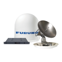
Interfaces and configuration for the STM SatLink 2900 VSAT modem.
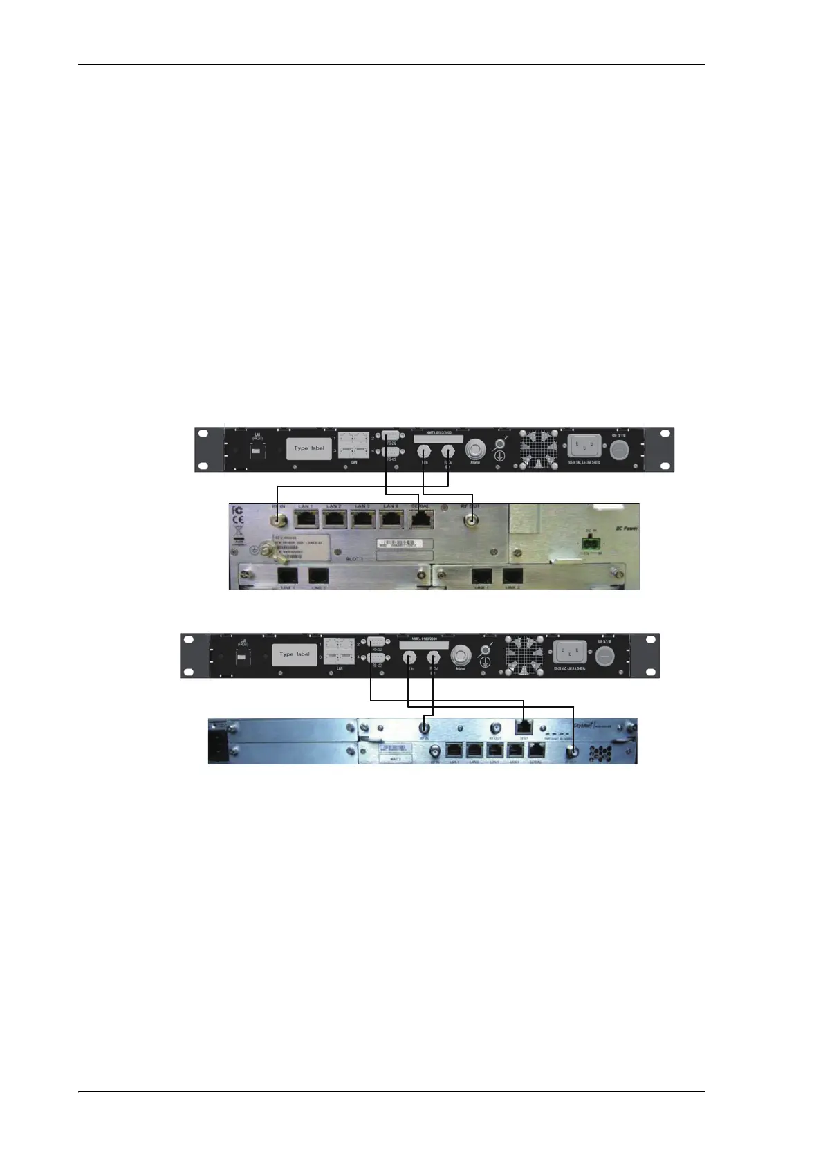
Interfaces and configuration for the Gilat SkyEdge II VSAT modem.
Interfaces and configuration for the Inmarsat G5 modem.
Protocols and configuration examples for the Linkway S2 modem.
Overview of using Telnet for configuring the FV-110 and VSAT modem.
Detailed description of supported commands for the FV-110 command line interface.
Provides sample satellite data for azimuth calibration purposes.
Explains the necessity of grounding for safety and equipment protection.
Provides guidelines for grounding the ACU and ADU to the ship's hull.
Alternative grounding methods for steel hull installations.
Alternative grounding methods for aluminum hull installations.
Alternative grounding methods for fiber glass hull installations.
Details on the construction and connection of a separate ground cable.
Recommendations for mitigating RF interference issues.
General overview of event messages detected by the FV-110 system.
A list of error and warning messages related to the ADU.
A list of error and warning messages related to the ACU.
Lists the various approvals obtained for the FV-110 system.
Original Equipment Manufacturer declaration for the FV-110.
CE certification details for the FV-110 system.
Summary sheet of Eutelsat ESV approval for the FV-110.
Detailed specifications for the FV-110 Antenna Unit.
Detailed specifications for the FV-110 Antenna Control Unit.
Information on the ports and interfaces available on the ACU.
Specifications for the power supply unit and optional UPS.
List of VSAT modems supported by the FV-110 system.
Packing list item PL-1.
Packing list item PL-3.