Calibration
5-15
5. Enter the Modem CW frequency (Continuous Wave) in GHz.
This is provided by the satellite operator, typically when talking to the satellite
operator on the phone before starting the line up.
6. Set the values as advised by the service provider:
• TX polarisation
•Azimuth
• Elevation
7. If needed, add 90 degrees to the TX polarisation by selecting the field.
8. To save the TX polarisation offset value, click the button Save polarisation offset.
9. Follow the instructions from the service provider to make a P1dB compression test
(VSAT modem).
10.Click the button Deactivate to finish the line up procedure.
When finished, the saved value for TX polarisation is visible the next time the line up
procedure is selected.
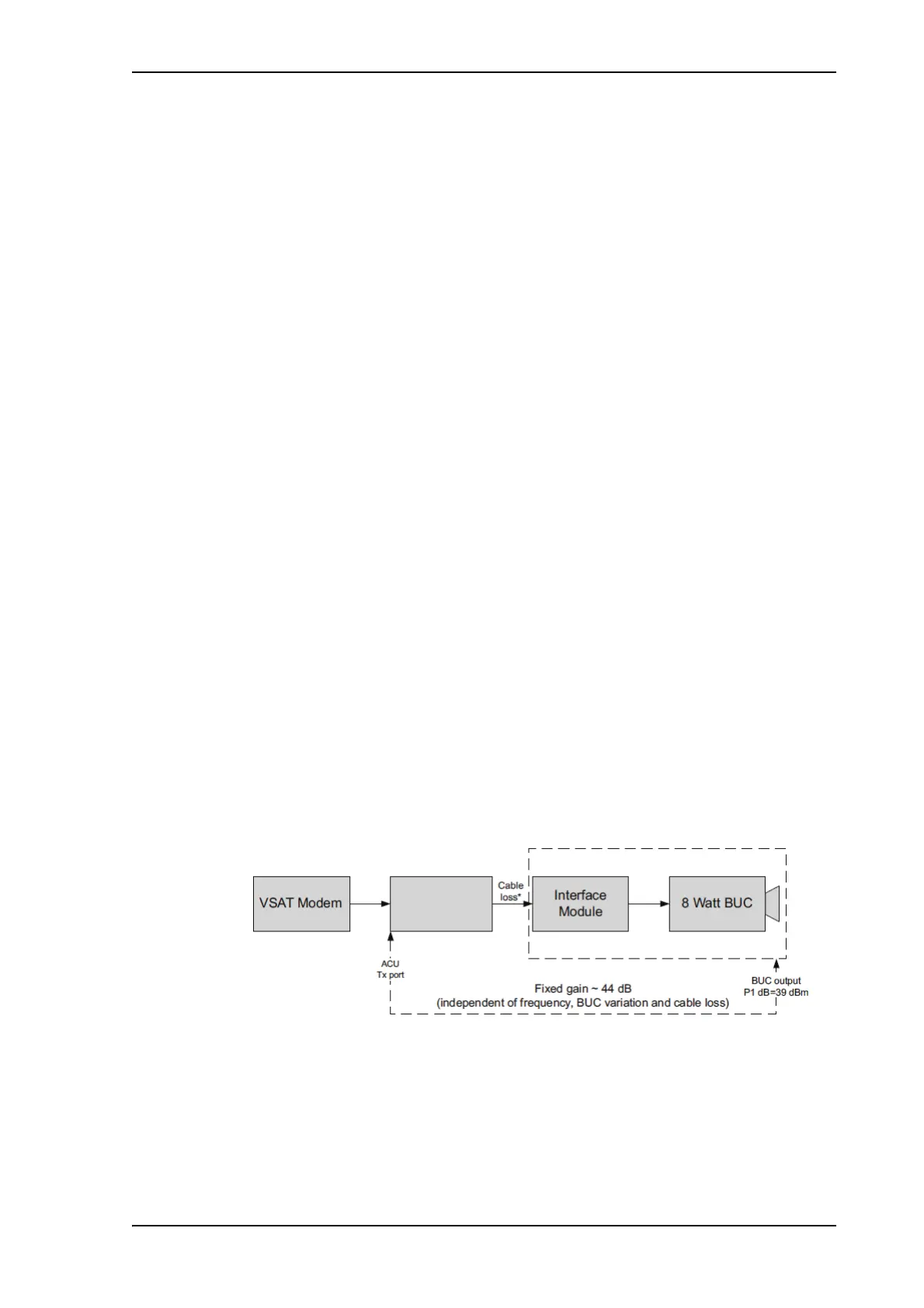
5.2.8 Fixed TX gain principle
The FV-110 uses a new transmitter chain concept. After calibration it provides a fixed
gain of 44 dB from the Tx-port of the ACU to the output of the BUC. Advantages of the
fixed TX gain principle are:
• Fixed TX gain over frequency and cable length
• TX gain independent of antenna cable length
• Utilization of the full 8W BUC power over frequency
• P1dB compression point the same over frequency
When installing the FV-110 you make a cable calibration. At that point every installation
finds the same P1dB compression setting regardless of cable length. The P1dB
compression point is approximately -5 dBm at the ACU Tx-port. Additionally the FV-110
system monitors the TX gain in real time.
Figure 5-13: Fixed TX gain principle (FV-110)
* You find the maximum cable loss at Maximum allowed RF loss in the ADU cable on
page 2-22.
Example: ACU Tx-port power: -5 dBm > BUC output = +39 dBm (compression)
 Loading...