3-1
Chapter 3
Interfaces
3
This chapter is organised in the following sections:
• Interfaces of the FV-110 ACU
• Interfaces of the VMU
3.1 Interfaces of the FV-110 ACU
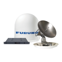
3.1.1 LEDs, display and keypad
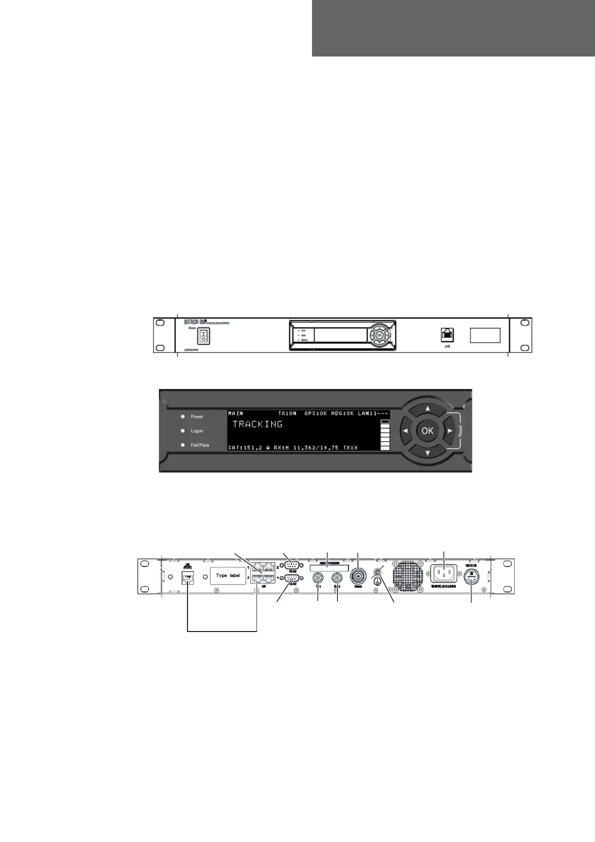
3.1.2 ACU connector panel — overview
The connector LAN on the front panel is typically connected to the service port at LAN3
with a straight Ethernet cable. Then you can access the service port from the front of the
ACU rack version.
Figure 3-1: ACU — LEDs, display and keypad
Figure 3-2: ACU: LEDs, display and keypad (detailed)
LAN3 (Service)
to front
NMEA
RS-232
RS-422
Ground
RX Out
TX In
LAN1 to 4
LAN1, 2: Modem Control
AC power
Fuse 7AT/SB
Antenna
Figure 3-3: ACU rack version, connector panel overview
 Loading...