Installation of the ACU
2-26
2.4 Installation of the ACU
The following sections describe the installation and grounding of the ACU.
When selecting a mounting location, keep in mind the following points:
• Locate the 19” rack where maintenance can easily be done.
• Separate the 19” rack 30 to 50 cm from a bulkhead.
2.4.1 To install the ACU
A cable relief bracket is already mounted when receiving the ACU. The cable relief is a
simple system to secure cables with cable strips. It offers a number of holders to which
you can secure the cables from the ACU. To install the 19” rack version of the ACU, do
as follows:
1. Slide the ACU into a 1U space in a 19” rack.
2. Mount the screws in each side through the holes in the front and fasten the screws to
the rack. Make sure that the unit is mounted securely using the optional support
bracket according to the requirements for your 19” rack.
3. Connect all cables. See Interfaces of the FV-110 ACU on page 3-1 for a description of
the ACU connectors.
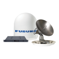
4. Set the On/Off switch at the front of the ACU to On.
For a description of the connectors see ACU connector panel — overview on page 3-1.
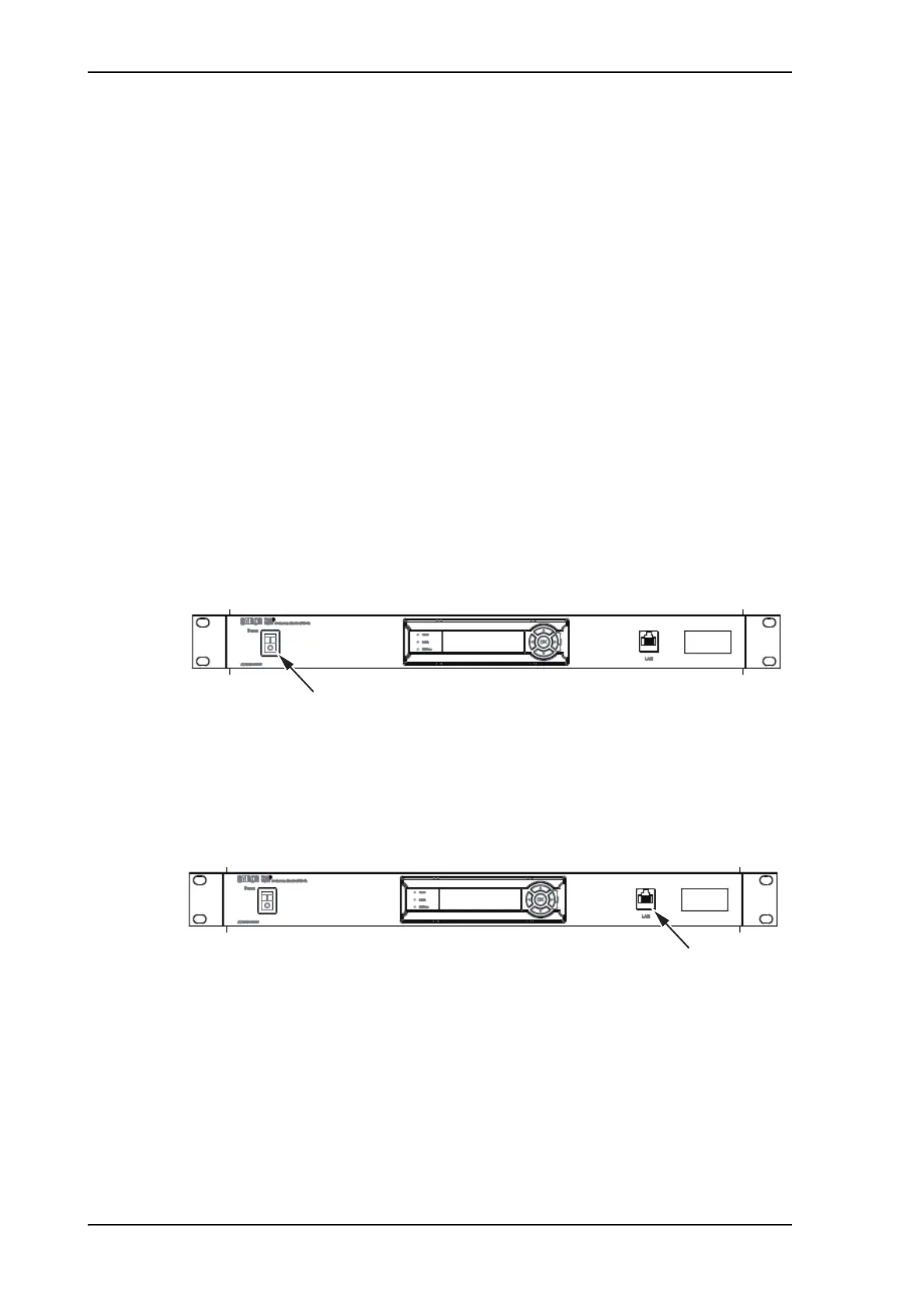
The ACU has additionally a LAN connector at the front for accessing the service port
from the ACU front panel.
Figure 2-22: ACU, On/off switch
Figure 2-23: ACU, LAN connector at the front: Service port
Service port
 Loading...