CGCOMMUNICATIONS GUIDE PROFIBUS-DP COMMUNICATIONS
369 MOTOR MANAGEMENT RELAY – COMMUNICATIONS GUIDE CG9
2.4 369 Relay Profibus-DP Diagnostics
The 369 Motor Management Relay supports both slave mandatory (6 bytes system-wide
standardized) and slave specific diagnostic data. If the diagnostics are considered high
priority, the PLC/host program will be informed of the fault (alarm or trip) and can call a
special error routine.
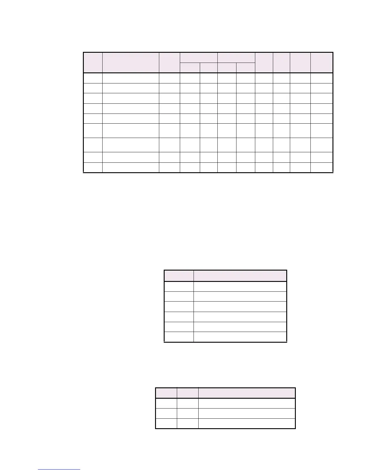
Diagnostic bytes 1 through 6 represent standard diagnostic data and are formatted as
follows.
The extended diagnosis for the relay is composed of 26 bytes (bytes 7 to 32) and contains
diagnostic information according to the following table.
202 Last pre–trip Vca 2 0 0000 65000 FDE8 1 V F1 0
204 Last pre–trip Van 2 0 0000 65000 FDE8 1 V F1 0
206 Last pre–trip Vbn 2 0 0000 65000 FDE8 1 V F1 0
208 Last pre–trip Vcn 2 0 0000 65000 FDE8 1 V F1 0
210 Last pre–trip Frequency 2 0 0000 12000 2EE0 1 Hz F3 0
212 Last pre–trip KiloWatts 2
–
32000
8300 32000 7D00 1 kW F4 0
214 Last pre–trip KiloVAR 2
–
32000
8300 32000 7D00 1 kvar F4 0
216 Last pre–trip KiloVA 2 0 0000 50000 C350 1 kVA F1 0
218 Last pre–trip PowerFactor 2 –99 FF9D 100 0064 1 – F21 0
Table CG–1: Profibus Input Data (Sheet 4 of 4)
OFFSET CYCLIC DATA
(ACTUAL VALUES)
LENGTH
(BYTES)
MINIMUM MAXIMUM STEP
VALUE
UNITS FORMAT
CODE
DEFAULT
VALUE HEX VALUE HEX
Table CG–2: Diagnostic bytes 1 through 7
BYTE DESCRIPTION
1Station Status 1
2Station Status 2
3Station Status 3
4 Diagnostic Master Address
5 Identification Number (High Byte)
6 Identification Number (Low Byte)
Table CG–3: Profibus Diagnostics (Sheet 1 of 7)
BIT BYTE FUNCTION
0 to 7 7 Number of Diagnostic Bytes
0 8 SinglePhasingTrip
1 8 SpareSwitchTrip

 Loading...


