CG46 369 MOTOR MANAGEMENT RELAY – COMMUNICATIONS GUIDE
MEMORY MAP CGCOMMUNICATIONS GUIDE
• Total Logs Since Last Clear: This value indicates the number of Logs that have been
generated since the Data Logger was last cleared. Although it's maximum range is
65535, the 369 will only retain up to the latest 50 records.
• Total Logs Presently Used: This value indicates the total number of Logs that have
been captured and are presently available in the 369.
• Total Records Presently Used: This is the number of records that have been written
into the Data Log and are presently available in the 369.
• Log Status: This reports the current status of the Data Logger (Running or Stopped).
• Log Time Remaining Until Next Reading: This is a counter showing how much time
remains until the next record is to be written into the Data Log (1~3600s).
• Data Logger Percentage Full: Indicates what percentage of the total available
memory is used.
• Pointer To Next Record To Write: This value points to the internal data address of the
location of the next record to be written.
• Pointer To Log (1-50) Starting Address : This value points to the internal data address
of the location of each of the potential 50 records.
• Log (1-50) Number of Records: This value provides the number of records that each of
the 50 potential Logs contain.
• Log (1-50) Start/Stop Method: This value is used to indicate the method by which each
log was started and stopped. If the bit value for the Start is zero, it was started by a
motor start event. Refer to Modbus format code F191 for more information on the
format of this data.
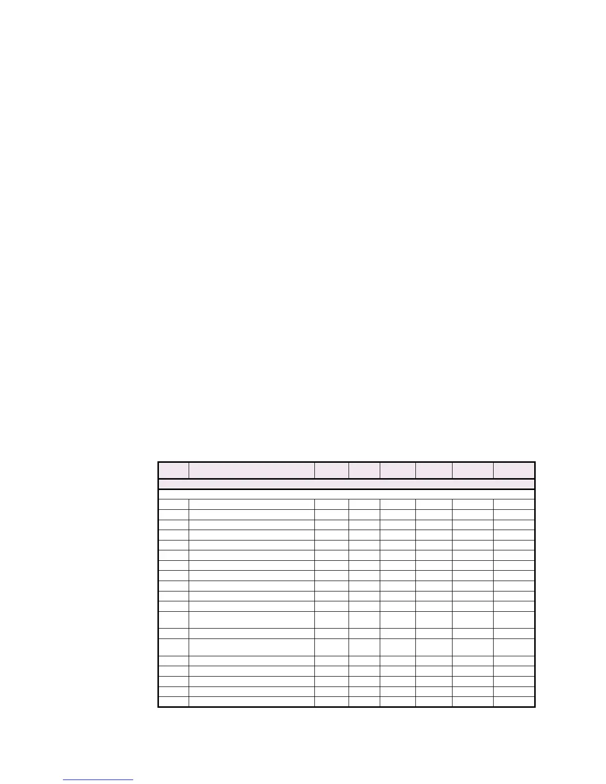
6.7 Modbus Memory Map
Table CG–10: MEMORY MAP (Sheet 1 of 57)
ADDR
(hex)
DESCRIPTION MIN. MAX. STEP
VALUE
UNITS FORMAT
CODE
FACTORY
DEFAULT
PRODUCT ID (ADDRESSES 0000 TO 007F)
PRODUCT ID
0000 GE Multilin Product Code - - - - F1 53
0001 Product Hardware Revision 1 26 1 N/A F15 A
0002 Firmware Revision N/A N/A N/A N/A F16 N/A
0003 Installed Modifications 0 65535 1 N/A F14 0
0004 Boot Revision 0 999 1 - F1 0
0005 Boot Modification Number - - - - - -
0006 Reserved - - - - - -
0007 Reserved - - - - - -
0008 Order Code 0 65535 1 N/A F13 0
↓↓ --- - - -
000F Modify Options 0 N/A - N/A N/A -
0010
Modify Options Passcode Characters
1 and 2
32 127 1 - F1 " "
↓↓ --- - - -
0017
Modify Options Passcode Characters
15 and 16
32 127 1 - F1 " "
--- --- - - - - - -
0020 Serial Number character 1 and 2 N/A N/A N/A ASCII F22 N/A
0021 Serial Number character 3 and 4 N/A N/A N/A ASCII F22 N/A
0022 Serial Number character 5 and 6 N/A N/A N/A ASCII F22 N/A
0023 Serial Number character 7 and 8 N/A N/A N/A ASCII F22 N/A

 Loading...


