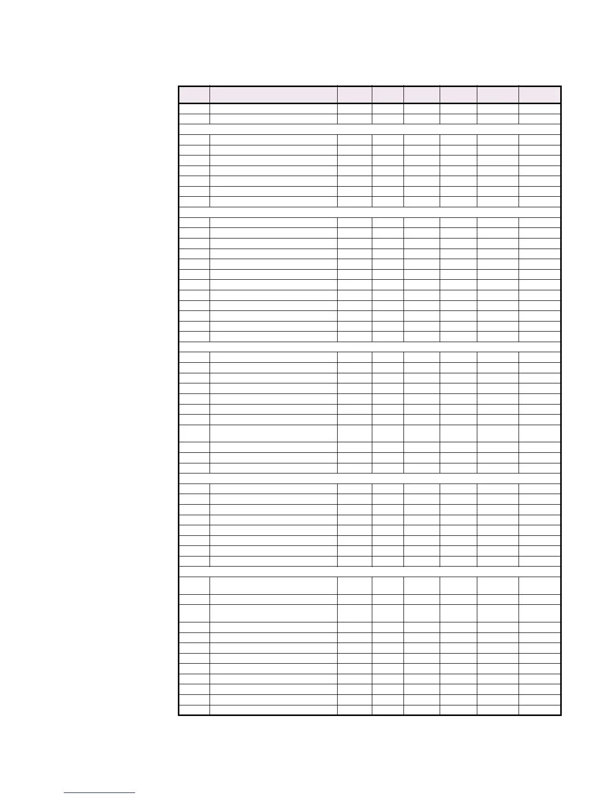
CGCOMMUNICATIONS GUIDE MEMORY MAP
369 MOTOR MANAGEMENT RELAY – COMMUNICATIONS GUIDE CG61
11C9 Assign Start Control Relays 0 7 1 - F113 2
... Reserved
REDUCED VOLTAGE
11CF Start Control Relay Timer 10 100 5 s F2 10
11D0 Reduced Voltage Starting 0 1 1 - F103 0
11D1 Assign Start Control Relays 0 7 1 - F113 4
11D2 Transition On 0 2 1 - F108 0
11D3 Incomplete Sequence Trip Relays 0 6 1 - F111 0
11D4 Reduced Voltage Start Level 25 300 1 % FLA F1 100
11D5 Reduced Voltage Start Timer 1 500 1 s F1 200
AUTORESTART
11D6 Autorestart 0 1 1 - F103 0
11D7 Total Restarts 0 65000 1 starts F1 1
11D8 Restart Delay 0 20000 1 sec. F1 60
11D9 Progressive Delay 0 20000 1 sec. F1 0
11DA Hold Delay 0 20000 1 sec. F1 0
11DB Bus Valid 0 1 1 - F103 0
11DC Bus Valid Level 15 100 1 %VT F1 100
11DD Reserved - - - - - -
11DE Autorestart Attempt Events 0 1 1 - F103 0
11DF Autorestart Success Events 0 1 1 - F103 0
11E0 Autorestart Aborted Events 0 1 1 - F103 0
... Reserved
UNDERVOLTAGE AUTORESTART
11F0 Enable UVR 0 1 1 - F30 0 (Off)
11F1 UVR Pickup Level 50 100 1 x RATED F3 65
11F2 UVR Assign Trip Relays 0 7 1 - F111 0
11F3 UVR Trip Delay 0 2550 1 x 0.1s F2 0
11F4 UVR Restoration Level 50 100 1 x RATED F3 90
11F5 Immediate Restart Power Loss Time 0 500 100 ms F1 0 (Off)
11F6 Delay1 Restart Power Loss Time 0 100 1 x 0.1s F2 0 (Off)
11F7 Delay2 Restart Power Loss Time 0 3601 1 s
F1 (3601=
Unlimited)
0 (Off)
11F8 Delay1 Restart Time Delay 0 12000 2 x 0.1s F2 20
11F9 Delay2 Restart Time Delay 0 12000 2 x 0.1s F2 100
11FA UVR Setup Time 0 12000 1 x 0.1s F2 100
DIGITAL COUNTER
12E6 First Character of Counter Name 32 127 1 - F1 “G”
12F2 First Character of Counter Unit Name 32 127 1 - F1 ‘U’
12F8 Counter Type 0 1 1 - F114 0
12F9 Digital Counter Alarm 0 2 1 - F115 0
12FA Assign Alarm Relays 0 6 1 - F113 0
12FB Counter Alarm Level 0 65535 1 - F1 100
12FD Reserved - - - - - -
12FE Record Alarms as Events 0 1 1 - F103 0
EMERGENCY
1330
1st & 2nd Character of Emergency Switch
Name
32 127 1 - F22 ’G’
1340 General Emergency Switch Type 0 1 1 - F116 0
1341
General Emergency Switch Block Input
From Start
0 5000 1 s F1 0
1342 General Emergency Switch Alarm 0 2 1 - F115 0
1343 General Emergency Switch Alarm Relays 0 6 1 - F113 0
1344 General Emergency Switch Alarm Delay 1 50000 1 100ms F2 50
1345 General Emergency Switch Alarm Events 0 1 1 - F103 0
1346 General Emergency Switch Trip 0 2 1 - F115 0
1347 General Emergency Switch Trip Relays 0 6 1 - F111 0
1348 General Emergency Switch Trip Delay 1 50000 1 100ms F2 50
1349 Emergency Switch Assignable Function 0 7 1 - F110 0
... Reserved
Table CG–10: MEMORY MAP (Sheet 16 of 57)
ADDR
(hex)
DESCRIPTION MIN. MAX. STEP
VALUE
UNITS FORMAT
CODE
FACTORY
DEFAULT

 Loading...


