CGCOMMUNICATIONS GUIDE MEMORY MAP
369 MOTOR MANAGEMENT RELAY – COMMUNICATIONS GUIDE CG63
141A Starter Aux Contact Type 0 1 1 - F109 0
141B Starter Operation Monitor Delay Time 0 60 1 seconds F1 0 (Off)
141C Starter Operation Monitor Type 0 2 1 - F115 0 (Off)
141D Starter Operation Monitor Relays 0 15 1 - F169 0 (None)
... Reserved
OUTPUT RELAY SETUP
1500 Trip Relay Reset Mode 0 2 1 - F117 0
1501 Alarm Relay Reset Mode 0 2 1 - F117 0
1502 Aux 1 Relay Reset Mode 0 2 1 - F117 0
1503 Aux 2 Relay Reset Mode 0 2 1 - F117 0
1504 Trip Relay Operation 0 1 1 - F161 0
1505 Alarm Relay Operation 0 1 1 - F161 1
1506 Aux1 Relay Operation 0 1 1 - F161 1
1507 Aux2 Relay Operation 0 1 1 - F161 0
... Reserved
FORCE OUTPUT RELAYS
1510 Assign Communications Force Relays 0 15 1 N/A F169 0
1511
Trip Communications Force Relay Output
Type
0 1 1 - F181 0
1512 Trip Pulsed Output Dwell Time 5 50000 1 100 ms F2 5
1513
Alarm Communications Force Relay
Output Type
0 1 1 - F181 0
1514 Alarm Pulsed Output Dwell Time 5 50000 1 100 ms F2 5
1515
Aux1 Communications Force Relay
Output Type
0 1 1 - F181 0
1516 Aux1 Pulsed Output Dwell Time 5 50000 1 100 ms F2 5
1517
Aux2 Communications Force Relay
Output Type
0 1 1 - F181 0
1518 Aux2 Pulsed Output Dwell Time 5 50000 1 100 ms F2 5
... Reserved
PROTECTION FUNCTION BLOCKING
1520 Log Blocking Events 0 1 1 N/A F30 0
1521 Block Undercurrent/Underpower 0 1 1 N/A F30 0
1522 Block Current Unbalance 0 1 1 N/A F30 0
1523 Block Incomplete Sequence 0 1 1 N/A F30 0
1524 Block Thermal Model 0 1 1 N/A F30 0
1525 Block Short Circuit and Backup 0 1 1 N/A F30 0
1526 Block Overload Alarm 0 1 1 N/A F30 0
1527 Block Ground Fault 0 1 1 N/A F30 0
1528
Block Starts Per Hour and Time Between
Starts
011 N/AF300
... Reserved
THERMAL MODEL (0 = Off)
1581 Overload Pickup Level 101 125 1 0.01xFLA F3 101
1582 Assign Thermal Capacity Trip Relay 0 7 1 - F111 1
1583 Unbalance k Factor (0=Learned) 0 29 1 - F1 0
1584 Running Cool Time Constant 1 500 1 min F1 15
1585 Stopped Cool Time Constant 1 500 1 min F1 30
1586 Hot/Cold Safe Stall Ratio 1 100 1 - F3 100
1587 RTD Biasing 0 1 1 - F103 0
1588 RTD Bias Minimum 0 198 1 °C F1 40
1589 RTD Bias Mid Point 0 199 1 °C F1 120
158A RTD Bias Maximum 0 200 1 °C F1 155
158B Thermal Capacity Alarm 0 2 1 - F115 0
158C Assign Thermal Capacity Alarm Relays 0 7 1 - F113 1
158D Thermal Capacity Alarm Level 1 100 1 % used F1 75
158E Thermal Capacity Alarm Events 0 1 1 - F103 0
158F Enable Learned Cool Time 0 1 1 - F103 0
1590 Enable Unbalance Biasing 0 1 1 - F103 0
1591 Motor Load Averaging Interval 3 60 3 cycles F1 3
... Reserved
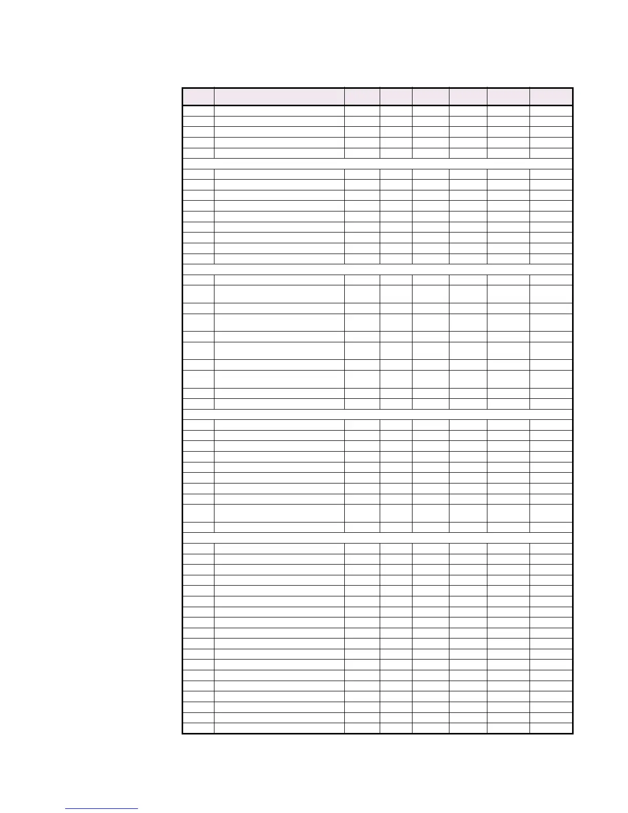
Table CG–10: MEMORY MAP (Sheet 18 of 57)
ADDR
(hex)
DESCRIPTION MIN. MAX. STEP
VALUE
UNITS FORMAT
CODE
FACTORY
DEFAULT

 Loading...


