258
INSTRUCTIONS FOR USE
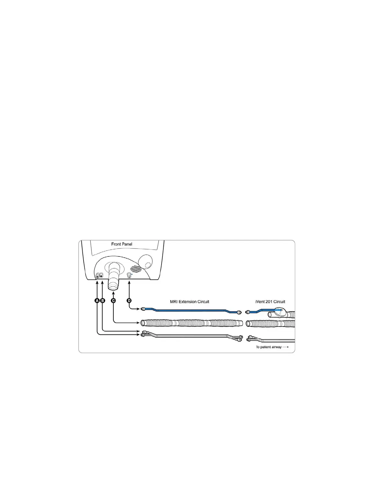
1. Stretch the 22 mm Extension Tube to the desired length.
2. On the front panel, connect the female end of the 22 mm Extension Tube to
the Ventilator Outlet (C) as shown in Figure 189
3. Connect the Flow Sensor Double Tubings (transparent tubes) from the
Extension Kit to their respective connectors near the Ventilator Outlet. The
Flow Sensor Tubings are equipped with luer connectors - left female (A) and
right male (B) to help differentiate between them.
4. On the right side of the front panel (D), connect the blue Exhalation Control
Tube with a luer connector to the Exhalation valve luer inlet.
5. Connect the open male side of the 22 mm Extension Tube to the female side
of the Patient Circuit.
6. On the open side, connect the two transparent Channel Flow Sensor luer
connectors to the respective luer connectors - the Flow Sensor in the Patient
circuit.
7. Connect the open Exhalation Control Tube with luer connector (blue tube) to
its respective Exhalation Valve luer connector in the Patient circuit.
8. Perform a full O.V.T procedure before starting ventilation (See The O.V.T. page
176).
Figure 189: iVent
TM
201 MRI Extension Circuit Attachment0.
INSTRUCTIONS FOR USE WITH THE HUMIDIFIER
See page 44 for instructions for connecting the Humidifier to the Patient circuit.
Connect the Extension tubing between the humidifier outlet and the iVent
TM
201
circuit.
 Loading...