3 Operating the iVentTM201 – Setting Modes and Parameters
61
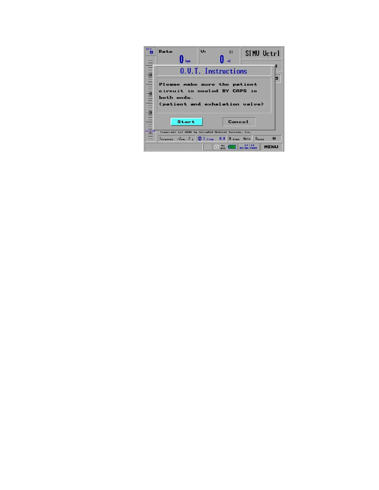
Figure 29: The Initial O.V.T Pop-Up Window
3. Follow the instructions on the screen. Use the plastic caps to seal off the
following:
The patient Wye sensor, and
The exhalation valve
4. Press the knob to begin the test. A pop-up window appears which indicates
the test has begun.
5. After several seconds, another pop-up window appears and instructs you to
remove the cap on the exhalation valve leaving the cap on the Wye
outlet.
6. After the ventilator performs further testing, it sounds an alarm. If you can
hear the alarm, press the Control Knob to complete the O.V.T. If remote
alarm is connected verify the alarm is activated in remote station.
Once the iVent
TM
201 has successfully completed the O.V.T., the patient circuit and
ventilator are ready for use.
If the O.V.T. fails:
1. Verify that both Flow Sensor tubes are properly and snugly connected to the
correct luer ports on the front of the iVent
TM
201. (Note: Remember that two
lines go to the patient Wye connectors, and the blue line goes to the
Expiratory Valve Control connector.) Repeat the test.
2. If the O.V.T. fails once again, then replace the patient circuit.
3. If after replacing the patient circuit, the O.V.T. still fails, try re-calibrating the
ventilator. If calibration fails to correct the O.V.T. failure, immediately remove
the ventilator from service and contact a Versamed approved technician.
STANDBY AND PATIENT VENTILATION
When you have selected the weight, the iVent
TM
201 enters Standby, ready to
ventilate the patient with a press of the Control Knob. By default iVent
TM
201
starts up in SIMV Volume control.
To start ventilation from Standby mode:
 Loading...