54
The amber charge LED lights to indicate that the iVent
TM
201 is connected to
external power.
The green on LED indicates that the power is switched on.
The Screen
The LCD screen is organized to allow rapid access to the ventilator’s functions.
The monitoring or control of any critical parameter is performed with ease.
Baseline indicators and alarms – emergency alerts and alert status
indicators, power and battery states, date and time, and the Menu access
button -- are all displayed along the bottom of the screen indicators.
Set values are displayed in black
Measured and calculated values are displayed in blue -- flashing values
indicate that a set value was not obtained.
Here is a quick overview of the most important screens:
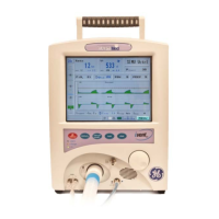
The Main Screen (Figure 26) is the first screen displayed when the iVent
TM
201 is
placed in Standby or Start Mode.
The slider gauge along the left side of the screen displays the real-time measured
Peak Inspiratory Pressure below a digital readout of the last peak inspiratory
pressure value.
On the top left of the screen, a large shows the total measured respiratory rate in
breaths per minute in large blue numbers. The selected/default respiratory rate
is shown in smaller black numbers below. Proceed to the Respiratory Rate
option to enable and change the number of breaths per minute.
Beside the Respiratory Rate option, there is also the Tidal Volume option. This
displays the exhaled Tidal Volume and allows adjustment to the set Tidal Volume.
(See page 69 for more details about the Tidal Volume display.)
On the top right of the screen is the Mode Selection option, which shows the
current ventilation mode. This option allows you to change modes (See page 62).
Selecting and clicking on a mode brings up the appropriate Mode screen for the
selected ventilation mode. Use this screen to view or adjust ventilation
parameters.
When the ventilator is operating, the middle section of the Main screen displays
pressure/flow waveforms. The optional waveforms package permits a host of
possible display characteristics. (See page 108 for a guide to the waveform
package.)

 Loading...