4 LINE PARAMETERS
This product requires information about the circuit to which it is applied. This includes line impedance, residual
compensation, and phase rotation sequence. For this reason circuit parameter information must be input using
the LINE PARAMETERS settings. These LINE PARAMETERS settings are used by protection elements as well as by the
fault locator.
4.1
TRIPPING MODE
The Tripping Mode setting selects whether the product should trip single-phase or three-phase when
instantaneous protection elements detect single-phase faults.
Selecting 1 and 3 Pole means that the product will only trip the affected phase for a single-phase fault. For
faults involving more than one phase the product will always trip all three phases.
Selecting 3 Pole means that the product will always trip all three phases.
For products controlling more than one circuit breaker, the tripping mode is independent for each circuit breaker.
The product features an autorecloser that can be used for single-phase autoreclose. In that case, if a single-phase
fault evolves into a multi-phase fault during the autoreclose cycle, the product will switch to three-phase tripping.
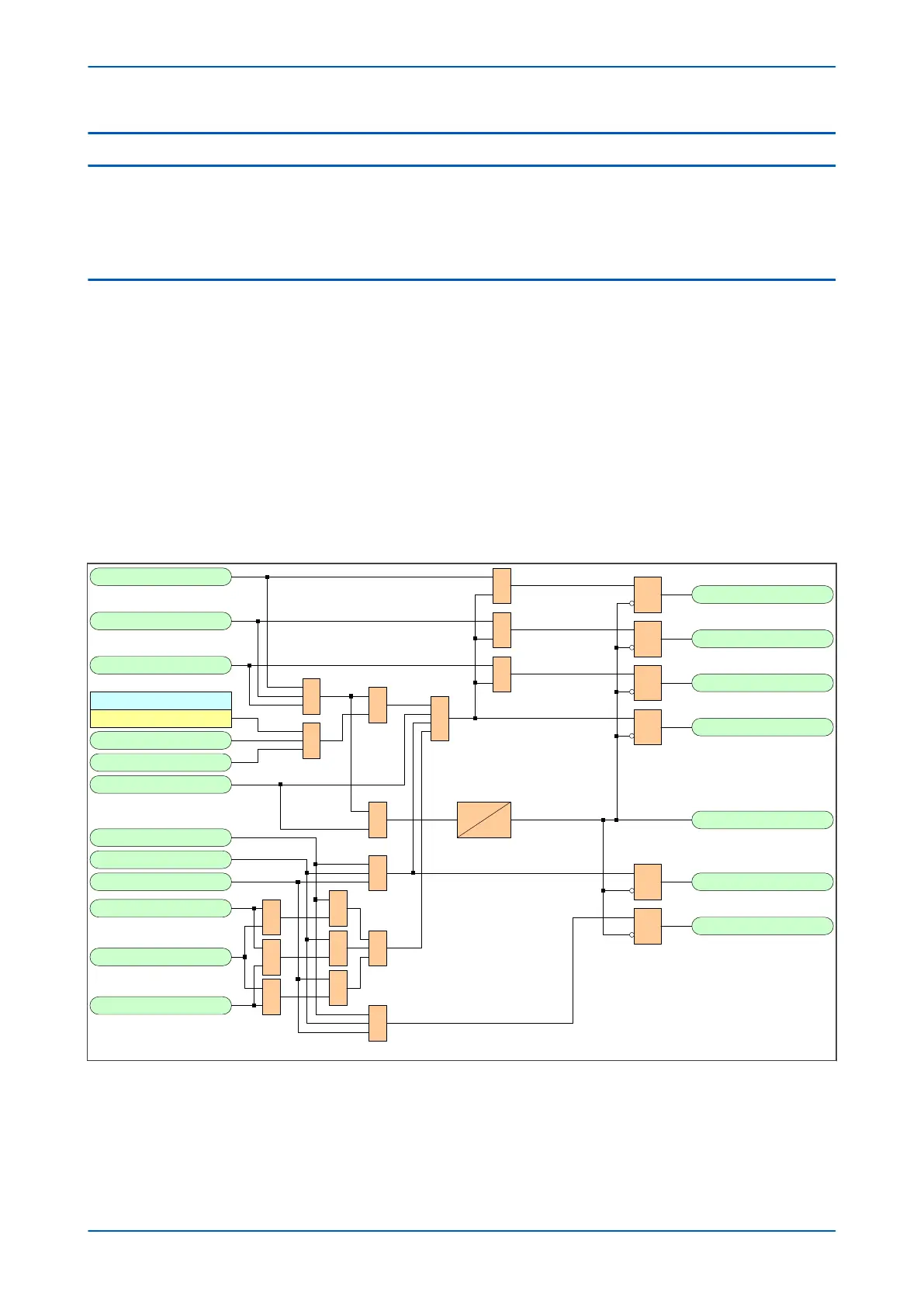
4.1.1
CB TRIP CONVERSION LOGIC DIAGRAM
V03386
Trip Inputs A
1
R
Q
S
Trip Output A
Trip Inputs B
1
R
Q
S
Trip Output B
Trip Inputs C
1
R
Q
S
Trip Output C
Tripping Mode
3 Pole
1
1
AR Force 3 pole
Force 3Pole Trip
Trip Inputs 3Ph
&
1
R
Q
S
Trip 3ph
1
Any Trip
Dwell
100 ms
1
1
1
Pole Dead A
Pole Dead B
Pole Dead C
Trip Inputs A
Trip Inputs B
Trip Inputs C
&
&
&
1
&
R
Q
S
R
Q
S
2/3 Ph Fault
3 Ph Fault
≥
2
530
531
532
858
533
529
530
531
532
892
893
894
523
524
525
526
522
527
528
Figure 33: Circuit Breaker Trip Conversion Logic Diagram (Module 63)
P543i/P545i Chapter 5 - Configuration
P54x1i-TM-EN-1 89

 Loading...


