The setting Rx Ph. Resistive defines the complete loop resistive reach R
LP
of the Distance Protection.
Since a phase-to-phase distance element measures half of the loop, the right-hand resistive reach R, of the
characteristic is equal to half of the setting value.
R = ½ Rx Ph. Resistive
+R
+jX
V02724
Z
V / I - R
V / I
R
Ð
Z
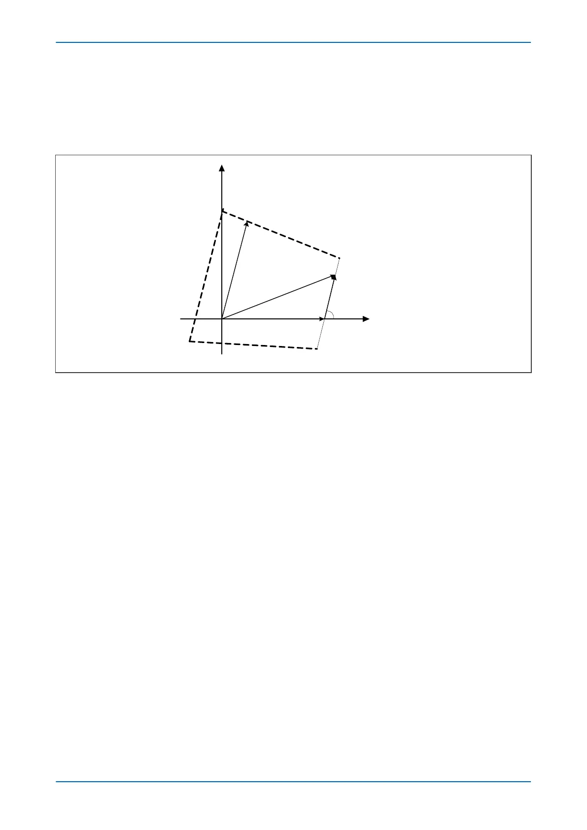
Figure 74: Resistive Reach line construction
For all V/I vectors which are on the left side of the right blinder the following condition is true:
Ð
(V/I - R)
£
Z
or
Ð
(V - I.R)
£
Ð
I. Z
The two signals provided to the comparator are:
S
1
= V - I.R
S
2
= I.Z
The impedance on the left side of the right hand resistive line is detected when the angle between S1 and S2 is
greater than 0°.
P543i/P545i Chapter 7 - Distance Protection
P54x1i-TM-EN-1 165

 Loading...


