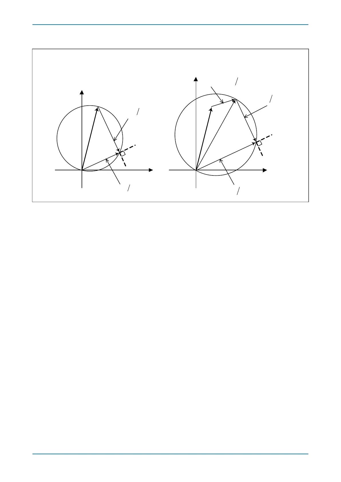
Figure 53: Directional Mho element construction – impedance domain
The two signals provided to the comparator are:
S
1
= V
S
2
= V - IZ
where (for an A-N fault for example) with residual compensation applied:
V = V
A
I = I
A
+ k
ZN
.I
N
where k
ZN
= (Z
0
- Z
1
) / 3Z
1
and is defined by two settings: kZN Res Comp and KZN Res Angle.
and if mutual compensation is applied:
I = I
A
+ k
ZN
.I
N
+ k
ZM
.I
M
where k
ZM
= 3Z
M
/ 3Z
1
and is defined by two settings: kZm Mutual Set and kZm Mutual Angle.
Operation occurs when the angle between the signals is greater than 90°.
To obtain a Z
LP
-plane representation in the directional Mho element construction, V is replaced with V
ph
and I is
replaced with I
ph
+ k
ZN
.I
N
, where V
ph
and I
ph
are the faulty phase voltage and current respectively (assuming no
mutual current compensation).
The two signals provided to the comparator in this case are:
S
1
= V
ph
S
2
= V
ph
- I
ph
.Z(1+k
ZN
.I
N
/I
ph
)
We can define a replica impedance reach, Z
replica
, as:
Z
replica
= Z(1+k
ZN
.I
N
/I
ph
)
or if mutual compensation is applied:
P543i/P545i Chapter 7 - Distance Protection
P54x1i-TM-EN-1 141

 Loading...


