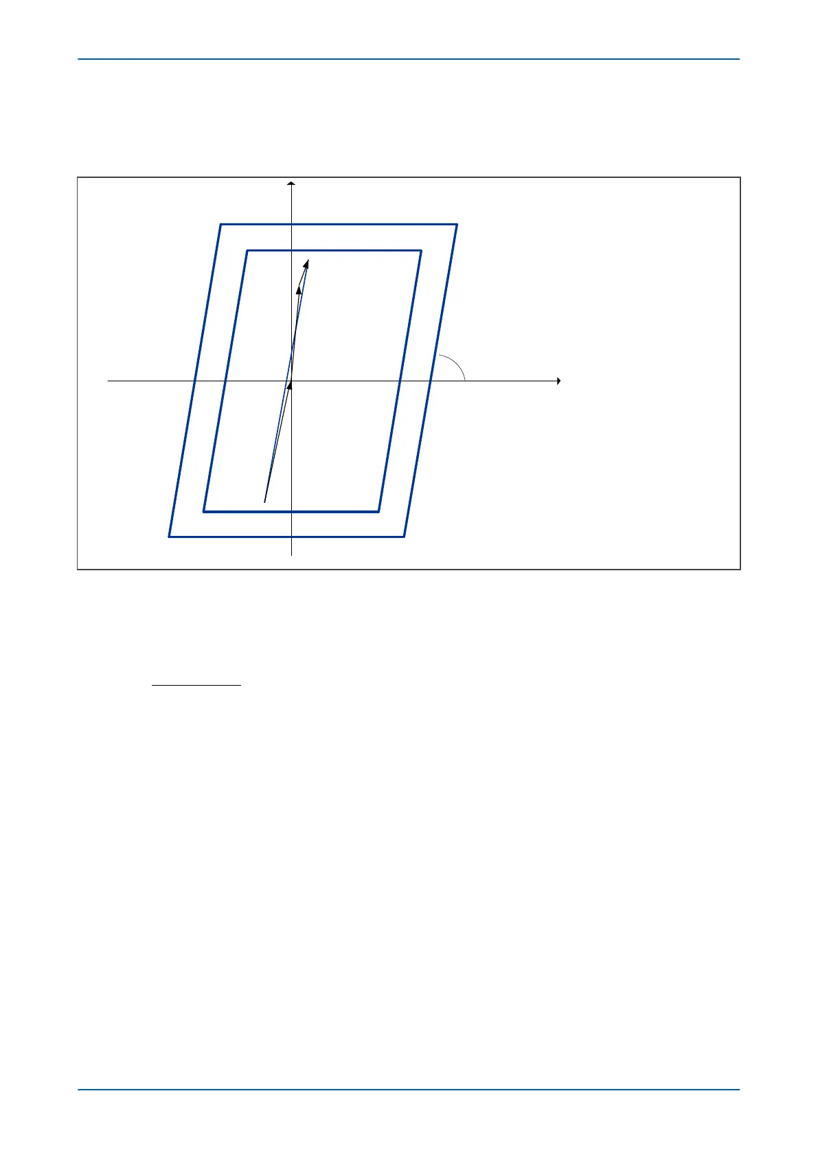
The angle Alpha should be set equal to the angle of the total impedance Z
T
:
a
=
Ð
Z
T
V02751
Zone 8
Zone 7
Resistive forward (+R)Resistive reverse (R’)
+jX
α = ÐZ
T
Z
T
Z
S
Z
L
Z
R
Figure 156: Reactive reach settings
3.6.3
PSB TIMER SETTING GUIDELINES
The Setting PSB Time setting can be calculated as follows:
where
●
angles q
1
and q
2
are defined in the following figure
● f
nom
is the nominal frequency
● f
PS
is the maximum Power Swing frequency to be taken into account
Since any power swing with f
PS
>= 0.5Hz can be detected by the setting-free delta current algorithm, only power
swings with f
PS
< 0.5Hz Hz need to be considered for Slow Power Swing detection. We recommended setting f
PS
to
1Hz because this value provides sufficient security margin.
P543i/P545i Chapter 10 - Power Swing Functions
P54x1i-TM-EN-1 281

 Loading...


