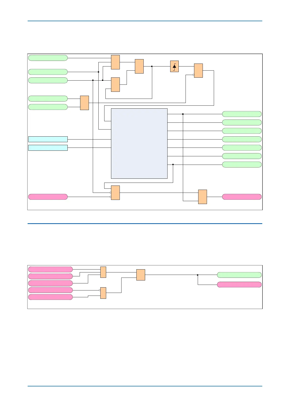
5.9.1 AUTORECLOSE SEQUENCE COUNTER LOGIC DIAGRAM
V03326
1
ARIP
AR Start
Seq Counter = 0
Seq Counter > 4
Seq Counter = 2
Seq Counter = 3
Seq Counter = 4
Seq Counter >Set
Prot Re-op
Single Pole Shot
Three Pole Shot
Sequence Counter
&
&
Seq Counter = 1
LastShot
Increment on rising edge
Reset on falling edge
&
S
R
Q
&
&
1P Dtime
Seq Counter = 1
AR Initiation
Figure 185: Autoreclose Sequence Counter logic diagram (Module 18)
5.10
AUTORECLOSE CYCLE SELECTION
The Autoreclose cycle selection logic is responsible for determining whether the Autoreclose will start as single-
phase or three-phase.
5.10.1
SINGLE-PHASE AUTORECLOSE CYCLE SELECTION LOGIC DIAGRAM
V03329
AR 1 pole in prog
CB1 L ARIP
CB1 L SPAROK
TMEM1PH
CB1 L ARIP
CB1 L 3 PAR
&
1
CB1 L SPAR
R
Q
S
Figure 186: Single-phase Autoreclose Cycle Selection logic diagram (Module 19)
Chapter 11 - Autoreclose P543i/P545i
328 P54x1i-TM-EN-1

 Loading...


