Note:
If the timer does not stop when the current is applied and stage 1 has been set for directional operation, the connections may
be incorrect for the direction of operation set. Try again with the current connections reversed.
16.4 PERFORMING THE TEST
1. Ensure that the timer is reset.
2. Apply a current of twice the setting shown in the I>1 Current Set cell in the OVERCURRENT column.
3. Note the time displayed when the timer stops.
4. Check that the red trip LED has illuminated.
16.5
CHECK THE OPERATING TIME
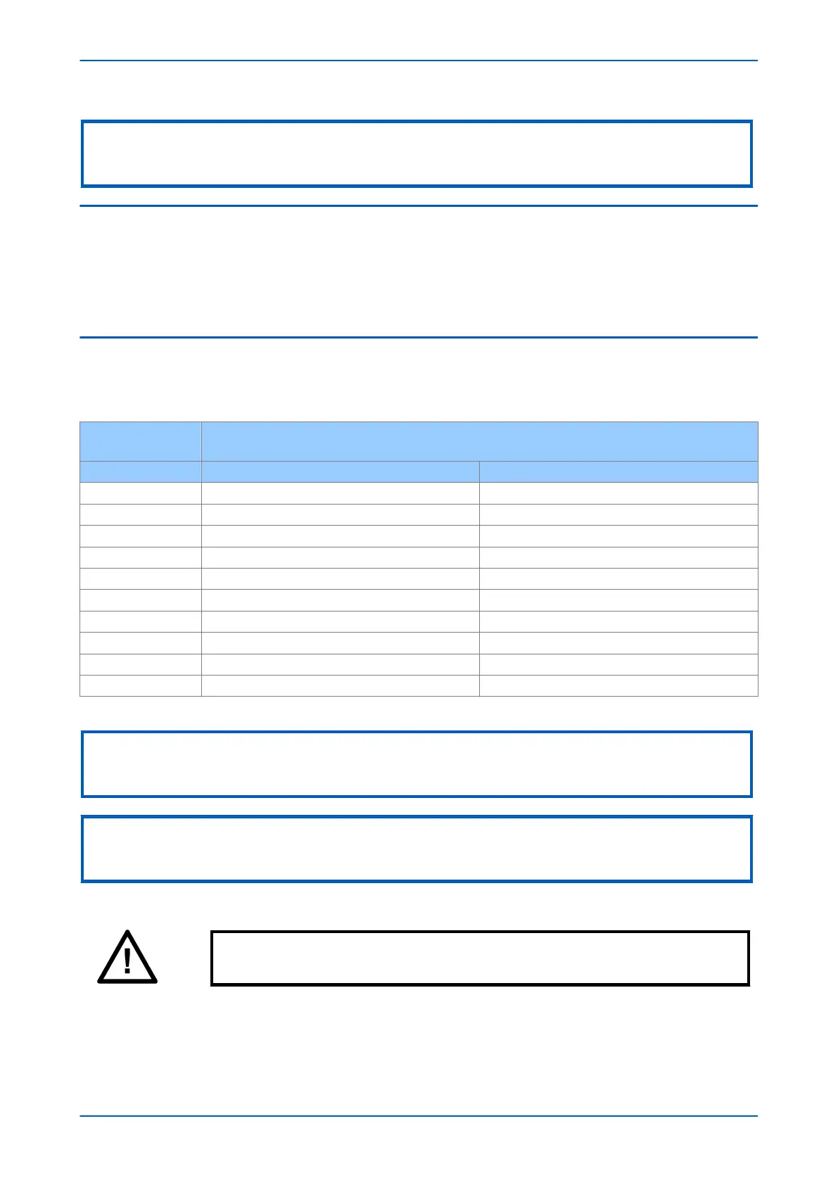
Check that the operating time recorded by the timer is within the range shown below.
For all characteristics, allowance must be made for the accuracy of the test equipment being used.
Characteristic
Operating time at twice current setting and time multiplier/
time dial setting of 1.0
Nominal (seconds) Range (seconds)
DT I>1 Time Delay setting Setting ±2%
IEC S Inverse 10.03 9.53 - 10.53
IEC V Inverse 13.50 12.83 - 14.18
IEC E Inverse 26.67 24.67 - 28.67
UK LT Inverse 120.00 114.00 - 126.00
IEEE M Inverse 3.8 3.61 - 4.0
IEEE V Inverse 7.03 6.68 - 7.38
IEEE E Inverse 9.50 9.02 - 9.97
US Inverse 2.16 2.05 - 2.27
US ST Inverse 12.12 11.51 - 12.73
Note:
With the exception of the definite time characteristic, the operating times given are for a Time Multiplier Setting (TMS) or Time
Dial Setting (TDS) of 1. For other values of TMS or TDS, the values need to be modified accordingly.
Note:
For definite time and inverse characteristics there is an additional delay of up to 0.02 second and 0.08 second respectively.
You may need to add this the IED's acceptable range of operating times.
Caution:
On completion of the tests, you must restore all settings to customer specifications.
P543i/P545i Chapter 25 - Commissioning Instructions
P54x1i-TM-EN-1 683

 Loading...


