6.5.3 INPUT BOARD
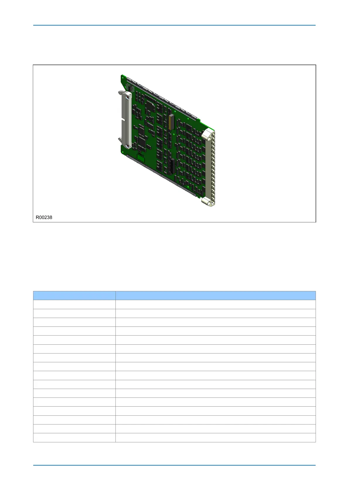
Figure 20: Input board
The input board is used to convert the analogue signals delivered by the current and voltage transformers into
digital quantities used by the IED. This input board also has on-board opto-input circuitry, providing eight optically-
isolated digital inputs and associated noise filtering and buffering. These opto-inputs are presented to the user by
means of a MD terminal block, which sits adjacent to the analogue inputs HD terminal block.
The input board is connected physically and electrically to the transformer board to form a complete input module.
The terminal numbers of the opto-inputs are as follows:
Terminal Number Opto-input
Terminal 1 Opto 1 -ve
Terminal 2 Opto 1 +ve
Terminal 3 Opto 2 -ve
Terminal 4 Opto 2 +ve
Terminal 5 Opto 3 -ve
Terminal 6 Opto 3 +ve
Terminal 7 Opto 4 -ve
Terminal 8 Opto 4 +ve
Terminal 9 Opto 5 -ve
Terminal 10 Opto 5 +ve
Terminal 11 Opto 6 -ve
Terminal 12 Opto 6 +ve
Terminal 13 Opto 7 –ve
Terminal 14 Opto 7 +ve
Terminal 15 Opto 8 –ve
Terminal 16 Opto 8 +ve
Chapter 3 - Hardware Design P543i/P545i
52 P54x1i-TM-EN-1

 Loading...


