V02764
Zone 6
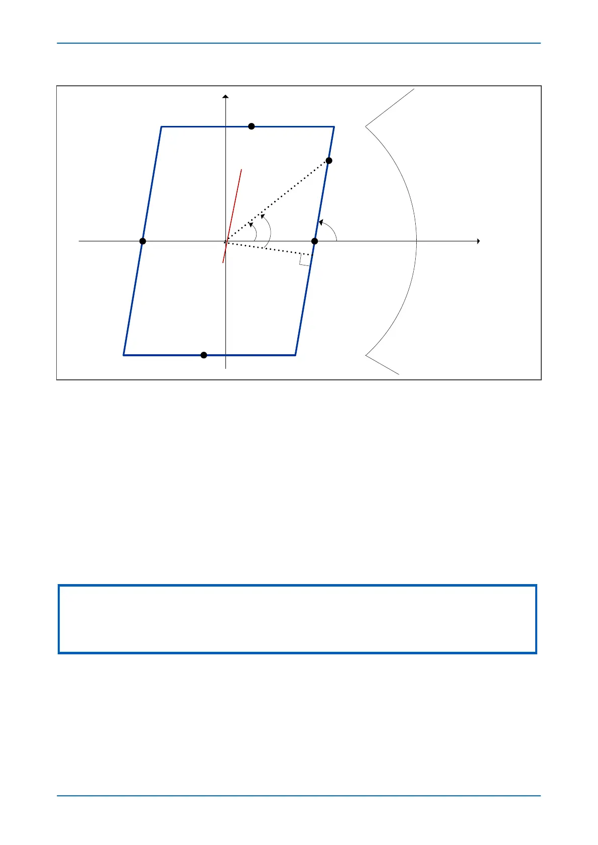
Resistive forward (+R)
Resistive reverse (R’)
α
OST Z6
OST Z6'
OST R6
OST R6'
+jX
Z
T
β
32°O
A
LOAD
Figure 161: OST R6max determination
β = 32 + 90 – α
Z load min = OA
Where:
● Z load min is the minimum load impedance radius
● 32º is the load angle that corresponds to the lower power factor of 0.85
● α is the load blinder angle (Blinder Angle) that matches the Z
T
angle
Therefore:
R6max < Z load min(Cos β)
Starting from the limit values R5min and R6max, the actual OST R5 and OST R6 reaches will be set in conjunction
with the Delta T setting.
Note:
The R6max reach must be greater than the maximum resistive reach of any distance zone to ensure correct initiation of the
25 ms and Delta T timers. However, the R5min reach could be set below the distance maximum resistive reach (inside the
distance characteristic) if an extensive resistive coverage is required, meaning that Out-of-Step protection does not pose a
restriction to the quadrilateral applications.
For each zone, we receommend setting the positive and negative limits to be the same so, OST R5’ = OST R5, OST
Z5’ = OST Z5, OST R6’ = OST R6, and OST Z6’ = OST Z6.
4.4.1.2 SETTING OST Z5 AND OST Z6
Setting of the reactance lines OST Z5 and OST Z6 depends on how far from the protection location the power
oscillations are to be detected. Normally, there is only one point for initial splitting of the system; and that point will
be determined by system studies. For that reason, the Out-of-Step protection must be enabled at that location and
Chapter 10 - Power Swing Functions P543i/P545i
288 P54x1i-TM-EN-1

 Loading...


