The cross-polarization voltage is generated using phase(s) not otherwise used for the particular distance or
directional measurement. While one pole is dead, and the memory is not available, the elements associated with
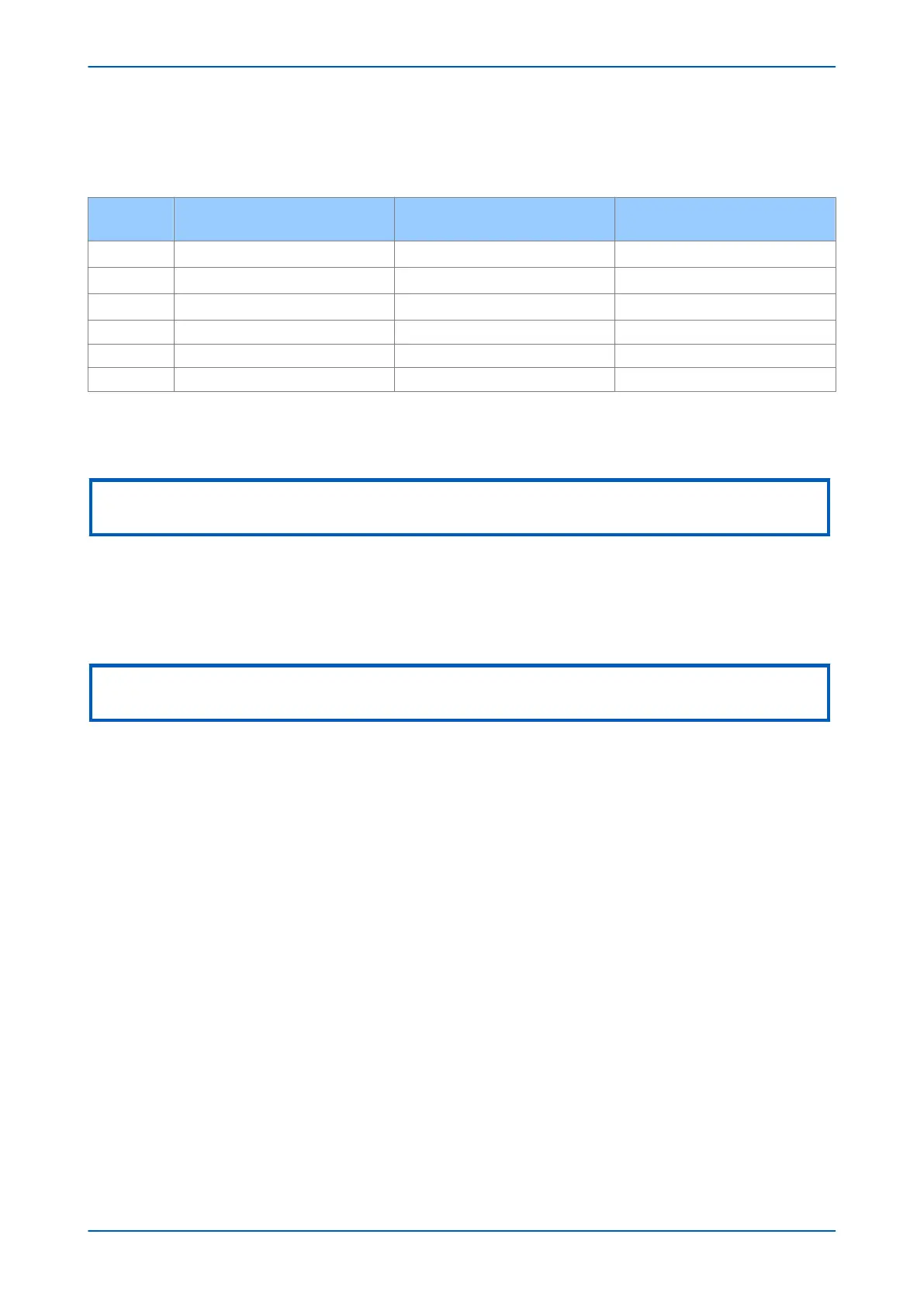
the remaining phases are polarized as shown in the following table:
Loop
Cross Polarizing Signal
(No poles dead)
Cross Polarizing Signal
Lagging Pole Dead
Cross Polarizing Signal
Leading Pole Dead
A-N
0.5(aVB + a
2
VC)
αVB α2VC
B-N
0.5(aVC + a
2
VA)
αVC α2VA
C-N
0.5(aVA + a
2
VB)
αVA α2VB
A-B
√3VC Ð -90º
0 0
B-C
√3VA Ð -90º
0 0
C-A
√3VB Ð -90º
0 0
where a is a mathematical operator which rotates a vector through 120° and a
2
denotes a rotation of 240°.
The table shows polarizing signal contributions for each loop under the different operating conditions. The
proportion of cross-polarization voltage used is defined by the Dist. Polarizing (p) setting.
Note:
Cross polarization is used only when there is no memory polarization quantity available.
3.1.8
IMPLEMENTATION OF MHO POLARIZATION
This product does not allow the directional Mho characteristics to be purely self-polarized or purely memory-
polarized. The polarizing voltage always contains the directly measured self-polarized voltage, onto which a
percentage of the pre-fault memory voltage is added.
Note:
If no memory voltage is available then the cross-polarized quantity is used instead.
The setting Dist. Polarizing (p) defines the amount of memory polarization (or if need be, cross polarization
voltage), which should be added with respect to the existing self-polarizing voltage so that:
S
1
= V + pV
mem
.
The value "p" can be set from 0.2 (20%) to 5 (500%).
This will have an affect on the characteristic where operation occurs when the fault impedance lies inside a circle
whose diameter is set by the points IZ and p/(1+p)IZ
source
This means for example:
● If p = 1, the characteristic will have an expansion of 50% I
Zsource
● If p = 5, the characteristic will have an expansion of 83.3% I
Zsource
The memory algorithm works as follows:
1. Memory voltage is stored for two cycles after line energisation, whereafter the voltage signals are
considered valid and stored in the voltage memory buffers. The voltage memory used for polarizing is taken
from a buffer corresponding to a value taken two cycles previously, so the voltage memory can be used
after four cycles following line energisation.
2. Following fault inception, voltage signals buffered in the polarizing memory can be recycled and re-used for
a period set with the Mem Volt Dura setting. This can be set between 16 and 32 cycles.
3. If a power swing condition is detected, the voltage memory signal expires after a reduced period of 3.2
cycles.
Chapter 7 - Distance Protection P543i/P545i
148 P54x1i-TM-EN-1

 Loading...


