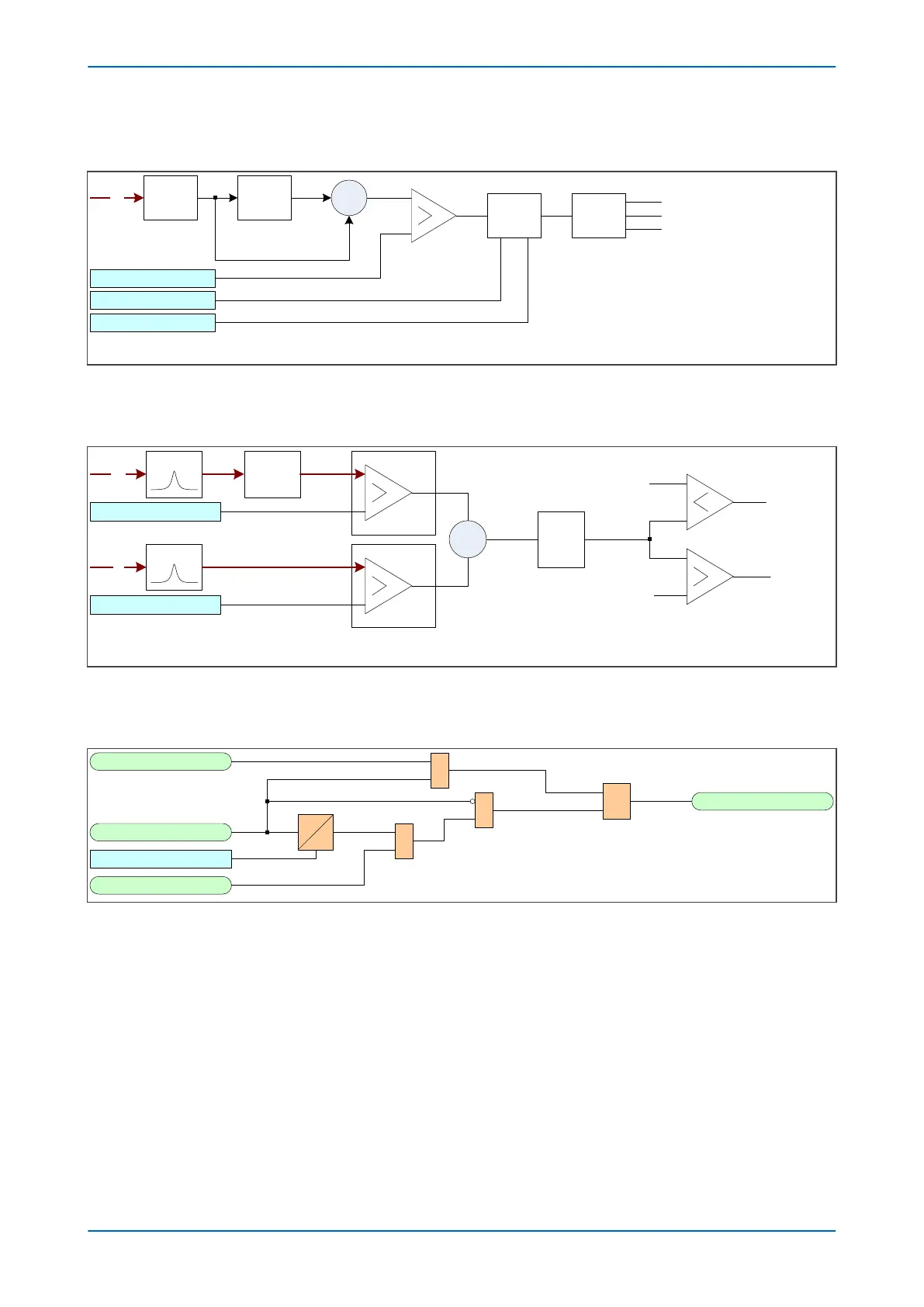
9.2.2 FAULT TYPE DETECTOR LOGIC
V00906
VN
Average
low pass
filter
FTD> VN
V
NRMS
Permanent
RMS
Ʃ
FTD> Time Window
FTD> Fault Count
-
+
Pulse
Counter
Decision Intermittent
Disturbance
Figure 229: Fault Type Detector Logic
9.2.3
DIRECTION DETECTOR LOGIC - STANDARD MODE
V00907
VN
Dir>Vnf Thresh
220Hz
Add 90°
phase shift
Sign filter
IN
Dir>Inf Thresh
220Hz Sign filter
X
V
H1
I
H2
Forward (faulty)
ò
Reverse (healthy)
Q
tran
-0.1
0.04
Note: In standard mode , Qtran comparison threshold is fixed at -0.1 for the
forward direction and +0.04 for the reverse direction.
Figure 230: Direction Detector Logic - Standard Mode
9.2.4
TRANSIENT EARTH FAULT DETECTION OUTPUT ALARM LOGIC
V00909
t
0
TEF Alarm Logic
TEF> Start
Reset TEF
TEF Alarm Output
R
Q
S
&
TEF> tRESET
&
1
Figure 231: TEFD output alarm logic
Chapter 13 - Current Protection Functions P543i/P545i
394 P54x1i-TM-EN-1

 Loading...


