Reverse. Other zones can be set independently as Offset, Directional Forward, or Directional Reverse. Each zone is
independent and is defined by an Impedance Reach Line, a Reverse Impedance Reach Line, and two resistive
blinders. The two resistive blinders (Resistive Reach Line and Reverse Resistive Reach Line) are parallel to the zone
characteristic impedance angle. The two reactance lines of each Quadrilateral exhibit a characteristic tilt. In the
phase fault characteristics the tilt of the Reverse Impedance Reach Line is preset, whilst you can choose the tilt
angle for the Impedance Reach Line.
3.3.1 PHASE FAULT IMPEDANCE REACH LINE
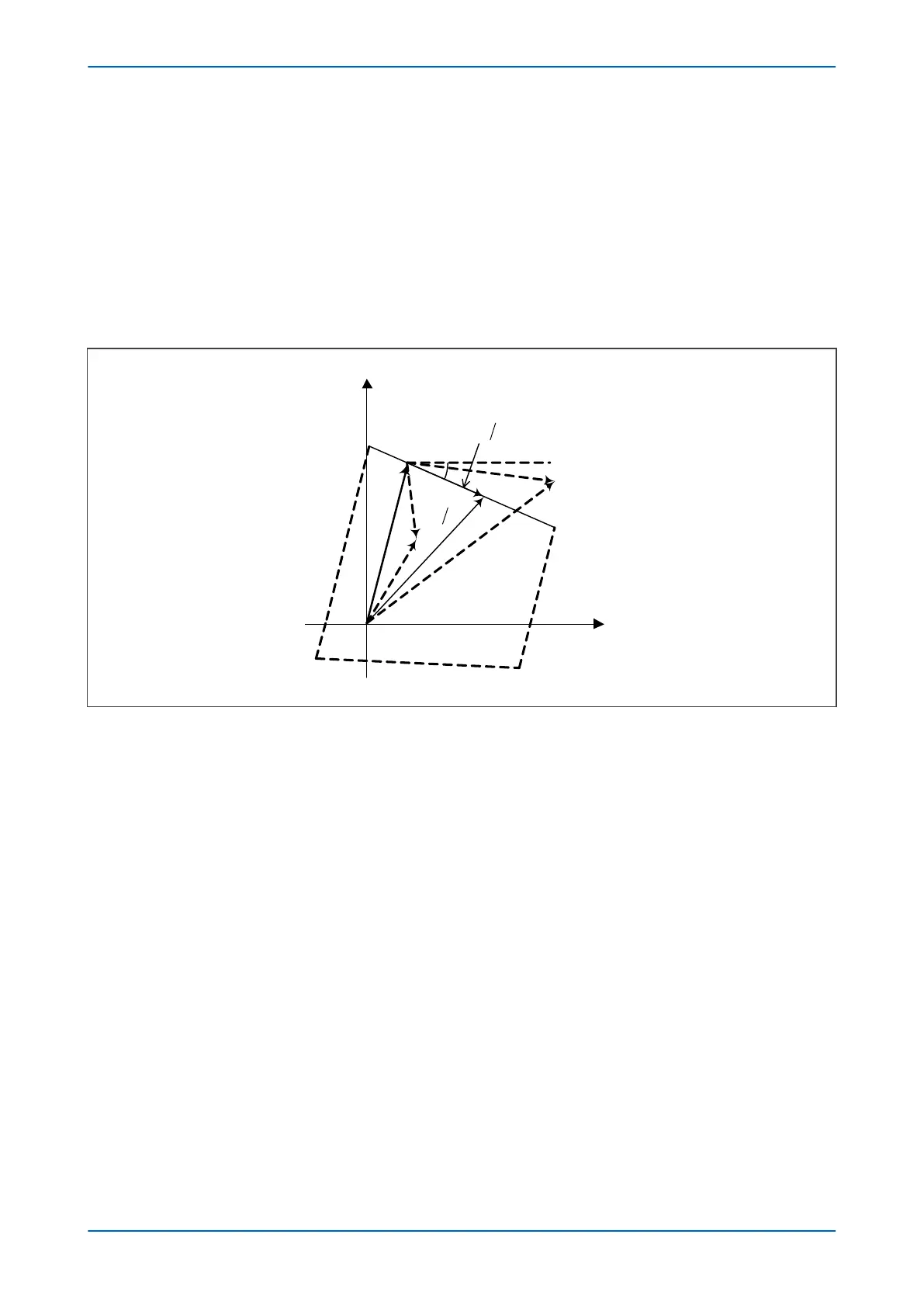
The tilt of the top line can be set independently for each zone. It is defined by a reach setting, Z, and a tilt angle, σ,
as shown in the following diagram:
Figure 71: Impedance Reach line construction
Referenced to the fault current I, the angle of tilt is equal to the setting σ. A negative angle sets a downward tilt
and a positive angle sets an upward tilt. Operation can occur when the operating signal lags the polarizing signal.
A negative angle sets a downward tilt and a positive angle sets an upward tilt.
For all V/I vectors below the Impedance Reach line, the following condition is true:
Ð
(V/I - Z)
£
σ
or
Ð
(V - I.Z)
£
Ð
I.
Ð
σ
The resultant two signals provided to the comparator are:
S
1
= V - I.Z
S
2
= I.
Ð
σ
Impedance on the tripping side of the Impedance Reach line is detected when the angle between S1 and S2 is less
than 0°.
3.3.2
PHASE FAULT REVERSE IMPEDANCE REACH LINE
The Reverse Impedance Reach line of the phase quadrilateral elements has a tilt that is fixed at -3° as shown in the
following diagram:
P543i/P545i Chapter 7 - Distance Protection
P54x1i-TM-EN-1 163

 Loading...


