The figures below show the element reaches, and the simplified scheme logic of the Aided Directional Earth Fault
(Aided DEF) Blocking scheme.
DEF-Reverse DEF-Reverse
DEF IDMT
DEF Bu2
DEF Bu1
DEF Inst
Trip
A
Trip
B
DEF-Forward
CRx
CTx
CRx
CTx
DEF IDMT
DEF Bu2
DEF Bu1
DEF Inst
DEF-Forward
E03519
Start
Start
Stop
Stop
DEF-Reverse
DEF-Forward
DEF-Forward
DEF-Reverse
t
IDMT
t
Bu2
t
Bu1
t
IDMT
t
Bu2
t
Bu1
A
B
ZL
1 1
&
&
Figure 116: Aided DEF Blocking scheme
5.7
AIDED DEF LOGIC DIAGRAMS
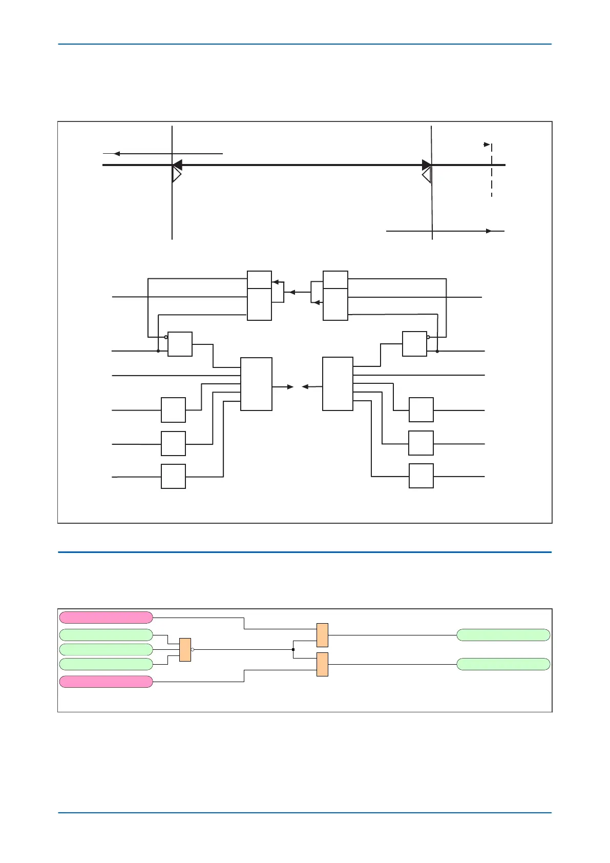
5.7.1 DEF DIRECTIONAL SIGNALS
V03526
Pole Dead A
DEF Forward element
DEF Reverse element
Pole Dead B
Pole Dead C
1
&
&
DEF Forward
DEF Reverse
892
893
894
996
997
Figure 117: DEF Directional Signals
P543i/P545i Chapter 8 - Carrier Aided Schemes
P54x1i-TM-EN-1 233

 Loading...


