EasyManuals Logo
Home>GE>Control Unit>P24DM

GE P24DM User Manual

GE P24DM
802 pages
To Next Page IconTo Next Page
To Previous Page IconTo Previous Page
Page #480 background imageLoading...
Page #480 background image
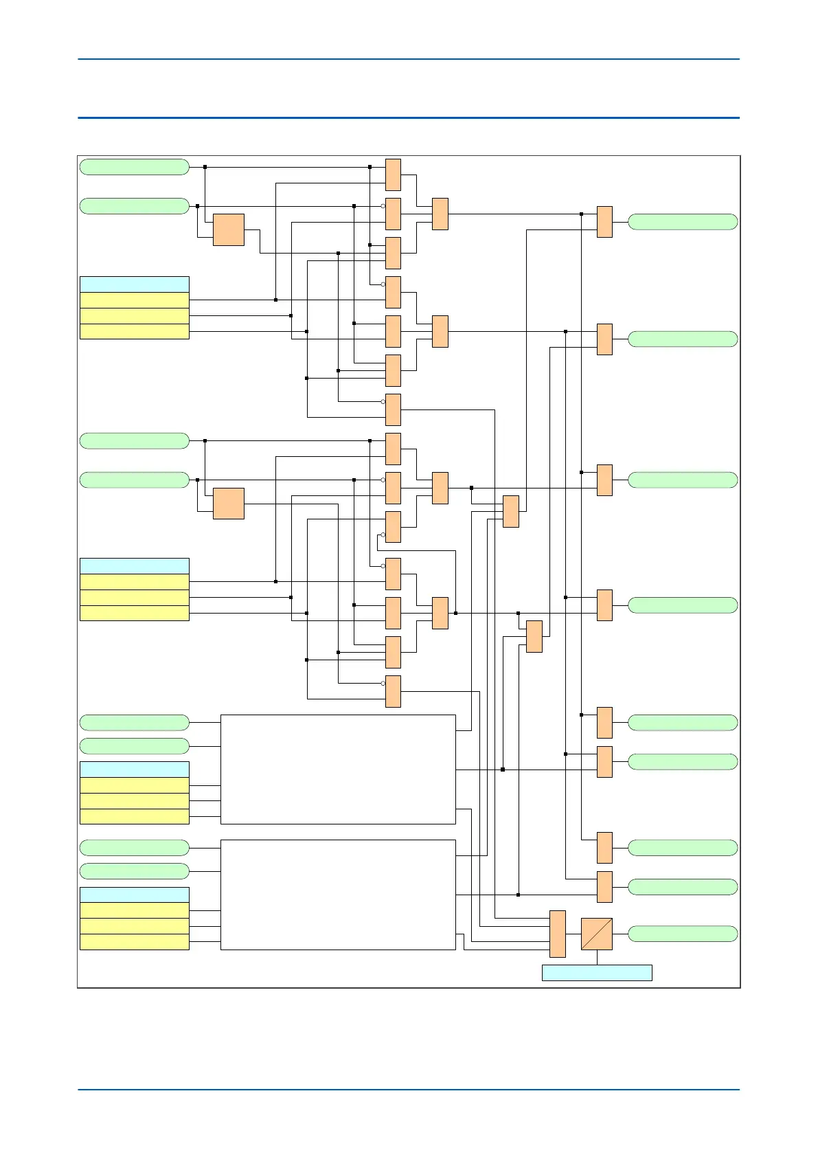
6.1 CB STATE MONITOR LOGIC DIAGRAM
V01264
CB Aux 3ph(52-A)
CB Aux 3ph(52-B)
CB Status Input
52A 3 pole
52B 3 pole
52A & 52B 3 pole
&
&
XOR
&
&
&
&
&
1
1 CB Closed 3 ph
1
CB Open 3 ph
1
CB Aux A(52-A)
CB Aux A(52-B)
CB Status Input
52A 1 pole
52B 1 pole
52A & 52B 1 pole
&
&
XOR
&
&
&
&
&
1
1
CB Aux B(52-A)
CB Aux B(52-B)
CB Status Input
52A 1 pole
52B 1 pole
52A & 52B 1 pole
CB Aux C(52-A)
CB Aux C(52-B)
CB Status Input
52A 1 pole
52B 1 pole
52A & 52B 1 pole
Phase B
(Same logic as phase A )
Phase C
(Same logic as phase A )
&
&
1
CB Closed A ph
1
CB Open A ph
1
CB Closed B ph
1
CB Open B ph
1
CB Closed C ph
1
CB Open C ph
CB Status Alm
1
CB Status Time
Figure 248: CB State Monitor logic diagram (Module 1)
Chapter 17 - Monitoring and Control P543i/P545i
444 P54x1i-TM-EN-1

Table of Contents

Questions and Answers:

Question and Answer IconNeed help?

Do you have a question about the GE P24DM and is the answer not in the manual?

GE P24DM Specifications

General IconGeneral
BrandGE
ModelP24DM
CategoryControl Unit
LanguageEnglish

Related product manuals