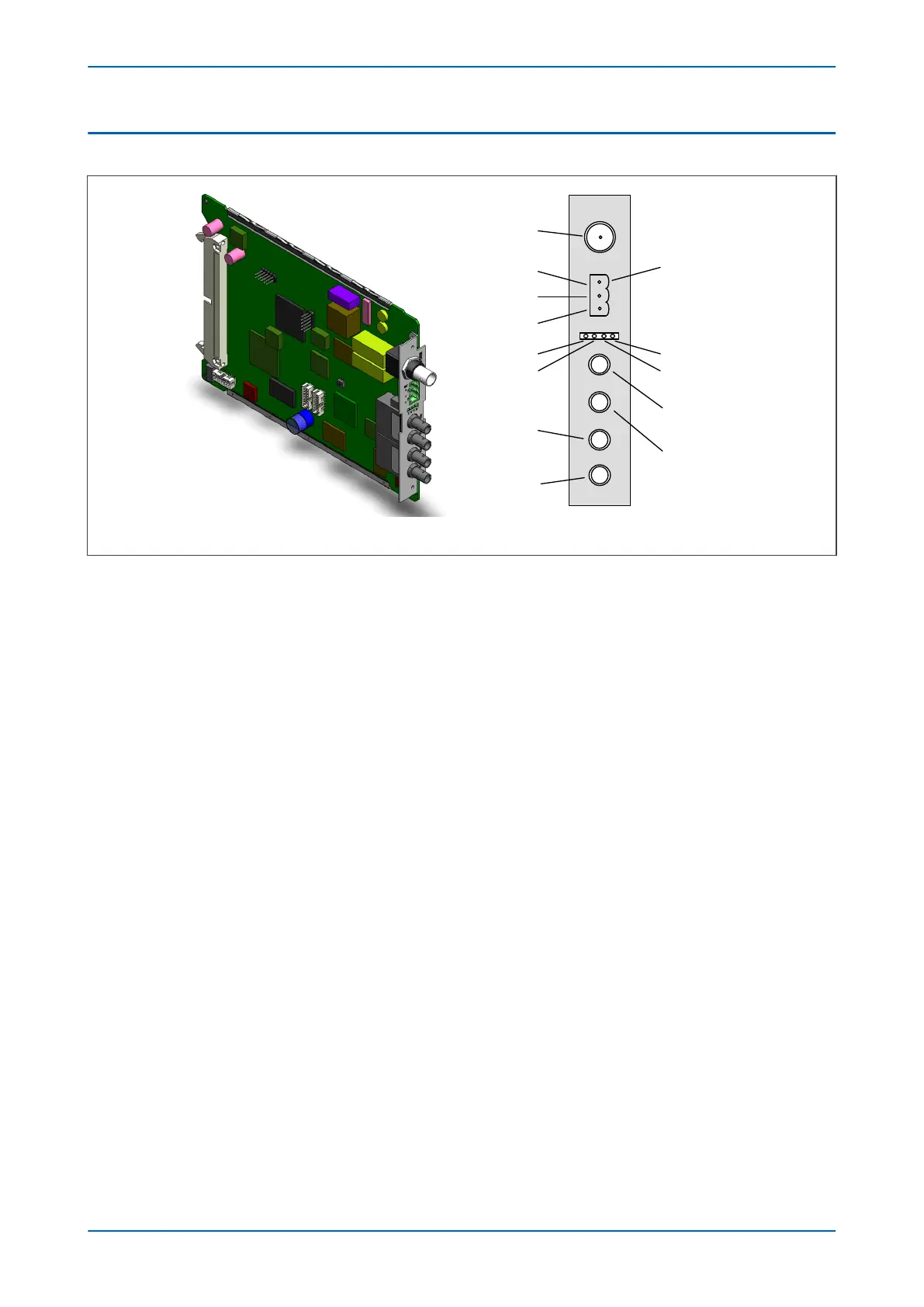
6.11 REDUNDANT ETHERNET BOARD
IRIG-B
Pin3
Link Fail
connector
Pin 2
Pin 1
Link channel
A (green LED)
Activity channel
A (yellow LED)
Link channel B
(green LED)
Activity channel B
(yellow LED)
A
B
C
D
V01009
Figure 26: Redundant Ethernet board
This board provides dual redundant Ethernet (supported by two fibre pairs) together with an IRIG-B interface for
timing.
Different board variants are available, depending on the redundancy protocol and the type of IRIG-B signal
(unmodulated or modulated). The available redundancy protocols are:
● SHP (Self healing Protocol)
● RSTP (Rapid Spanning Tree Protocol)
● DHP (Dual Homing Protocol)
● PRP (Parallel Redundancy Protocol)
There are several variants for this board as follows:
● 100 Mbps redundant Ethernet running RSTP, with on-board modulated IRIG-B
● 100 Mbps redundant Ethernet running RSTP, with on-board unmodulated IRIG-B
● 100 Mbps redundant Ethernet running SHP, with on-board modulated IRIG-B
● 100 Mbps redundant Ethernet running SHP, with on-board unmodulated IRIG-B
● 100 Mbps redundant Ethernet running DHP, with on-board modulated IRIG-B
● 100 Mbps redundant Ethernet running DHP, with on-board unmodulated IRIG-B
● 100 Mbps redundant Ethernet running PRP, with on-board modulated IRIG-B
● 100 Mbps redundant Ethernet running PRP, with on-board demodulated IRIG-B
The Ethernet and other connection details are described below:
IRIG-B Connector
● Centre connection: Signal
● Outer connection: Earth
Chapter 3 - Hardware Design P543i/P545i
58 P54x1i-TM-EN-1

 Loading...


