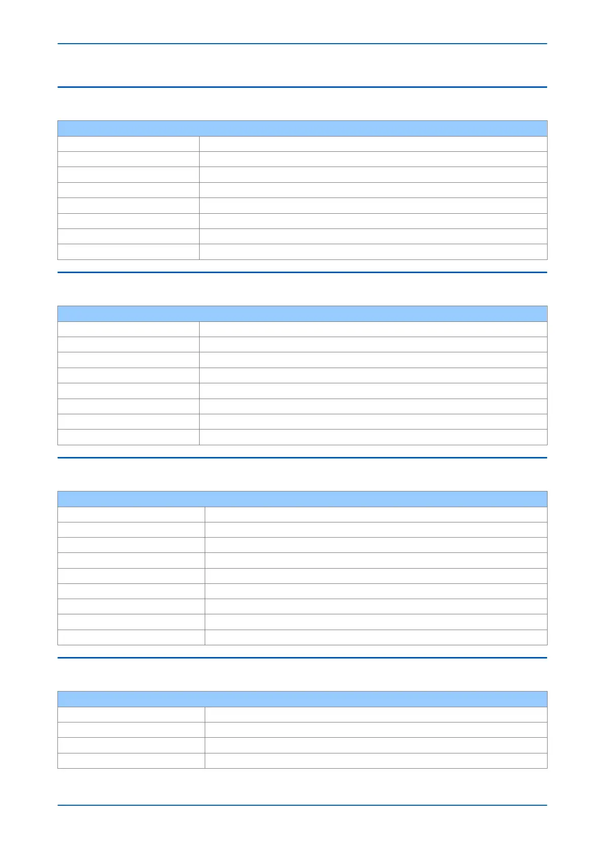
2.5 REAR SERIAL PORT 2
Optional rear serial port (RP2)
Use For SCADA communications (multi-drop)
Standard EIA(RS)485, K-bus, EIA(RS)232
Designation SK4
Connector 9 pin D-type female connector
Cable Screened twisted pair (STP)
Supported Protocols Courier
Isolation Isolation to SELV level
Constraints Maximum cable length 1000 m for RS485 and K-bus, 15 m for RS232
2.6 OPTIONAL REAR SERIAL PORT (SK5)
Optional rear serial port for teleprotection
Use For teleprotection in distance products
Standard EIA(RS)232
Designation SK5
Connector 9 pin D-type female connector
Cable Screened twisted pair (STP)
Supported Protocols InterMiCOM (IM)
Isolation Isolation to SELV level
Constraints Maximum cable length 15 m
2.7 IRIG-B (DEMODULATED)
IRIG-B Interface (Demodulated)
Use External clock synchronisation signal
Standard IRIG 200-98 format B00X
Connector BNC
Cable type 50 ohm coaxial
Isolation Isolation to SELV level
Constraints Maximum cable length 10 m
Input signal TTL level
Input impedance 10 k ohm at dc
Accuracy < +/- 1 s per day
2.8 IRIG-B (MODULATED)
IRIG-B Interface (Modulated)
Use External clock synchronisation signal
Standard IRIG 200-98 format B12X
Connector BNC
Cable type 50 ohm coaxial
P543i/P545i Chapter 27 - Technical Specifications
P54x1i-TM-EN-1 719

 Loading...


